

CAD Design Tips
Fractory gives instant prices for STP, SLDPRT, IPT and DXF files. 3D CAD models can be used for both cutting and bending. DXF drawings only work for instant cutting price quotations.
For creating your CAD models, we have compiled a list of free CAD software.
3D Models
Convert your CAD models to STP before uploading them onto Fractory’s platform for instant manufacturing quotes. Our platform also supports file formats native to SolidWorks (.sldprt) and Autodesk Inventor (.ipt).
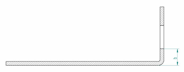
Recommended Minimum Flange Length and Inner Radius
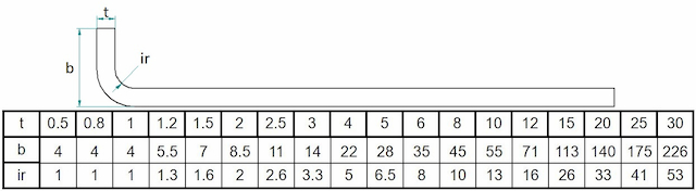
According to every sheet thickness, there’s a suitable inner radius and flange length when bending sheet metal.
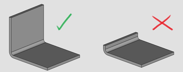
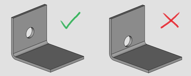
It is visibly clear that it is not possible to bend the part on the right. The flange is too short.
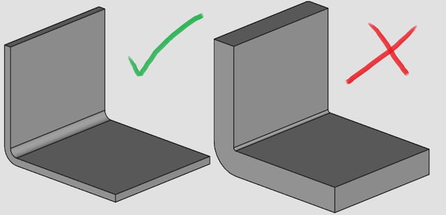
The radius for the part on the left has been chosen according to the bending table. Therefore, we can give an automated quote for that.
The part on the right is not producible. The inside radius is too small compared to the material thickness.
Chamfered Flange
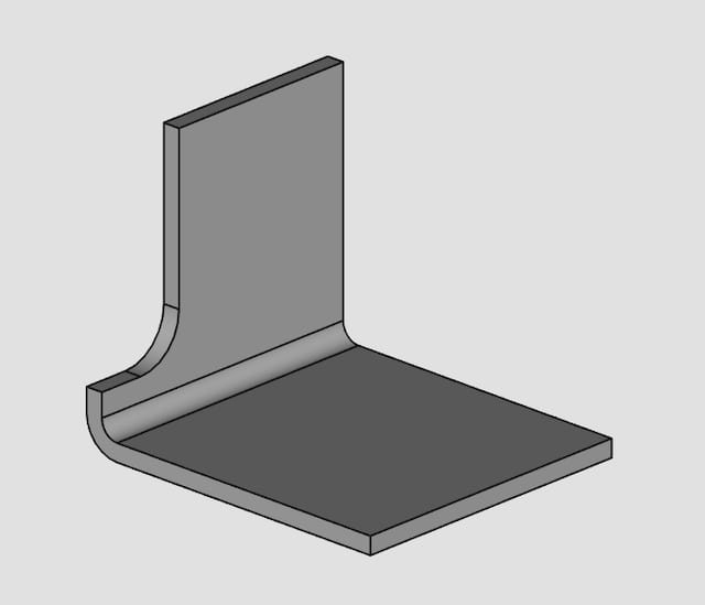
If the flange has a chamfer, the shortest side should be considered as flange length. See metal folding chart.
The danger with such parts is that the shorter part of the flange may get deformed during the bending operation.
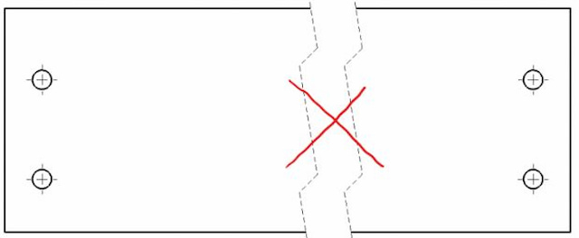
Hole Distance
Holes close to the bend may get deformed. Holes should be farther than the minimum recommended flange length. See metal folding chart.
The flange on the left is designed according to the rules in the bending table. Thus, the hole is far enough from the bend for an optimal result.
The part on the right has the hole too close to the bend and will get deformed.
Successive Bends
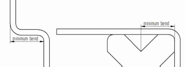
When you have successive bends, the minimum distance is the minimum flange length. See metal folding chart.
Bend Relief
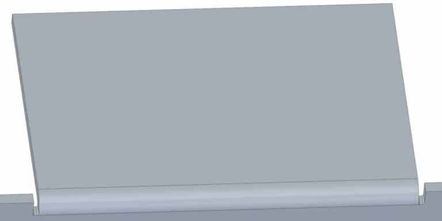
Use cut-outs next to flanges to avoid tearing the material during bending.
Max Dimensions for Sheet – 2980 x 1480 mm
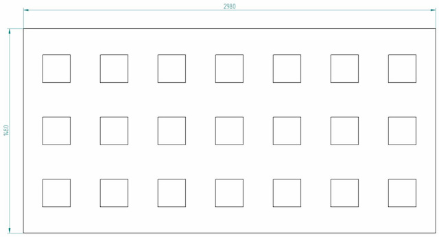
Although the standard sheet size is 3000×1500 mm, we have to cut off the edges to secure the proper positioning of the cutouts.
Tolerances on a Separate PDF
Specifications
Any specifications about metal surface treatment should be included in the commenting section.
Cutting Letters and Signs
The insides of letters will fall out unless connected to the part. A common mistake we see.
Cut to Normal
When making cuts in sheet metal environment, use the cut to normal function.
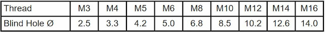
Threaded and Chamfered Holes
We can also do threading and countersinking. Indicate the number of threaded/countersunk holes on the ordering form to get an instant price.
Threading
The 3D models should include pilot holes for each threaded hole according to the table below but not the threads. Please attach a production file with relevant information about the threads.
Countersinking
Your 3D models should include the main hole but not the chamfers. Please attach a production file with relevant information about the chamfers.
Hole Distance
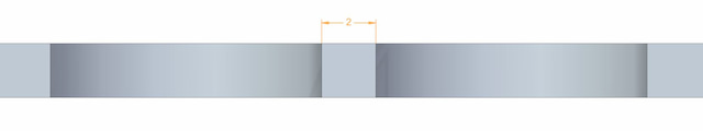
The distance between cuts should be equal to or more than the material thickness.
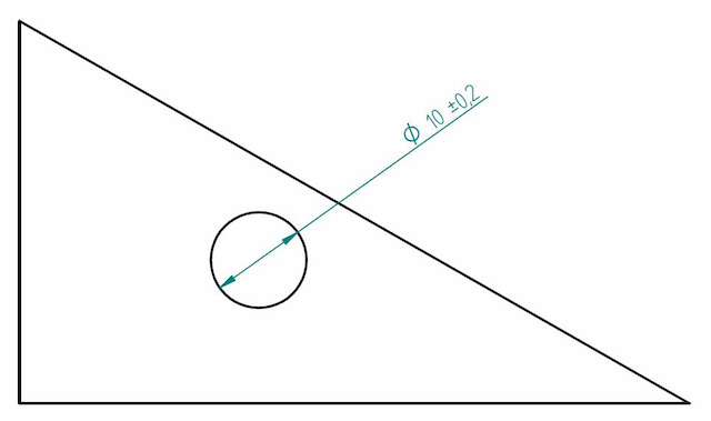
Hole Size
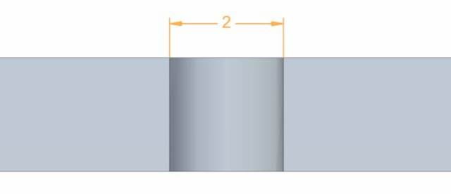
Holes should have a diameter equal to or more than the material’s thickness.
Add Radius to Tube
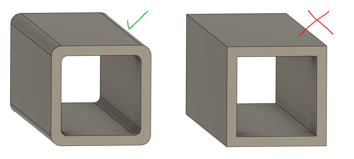
All rectangular tubes must have inside and outside radii, just like in real life. You can find the general radius rules here.
Should you not add the radii, your parts will be recognised as ones needing CNC machining.
Max Dimensions for Tube
The maximum length for tube cutting is 5800 mm.
No Holes on Tube Radius
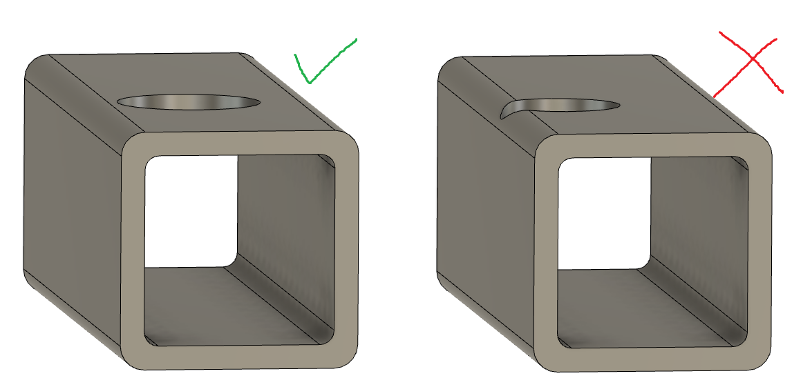
Avoid holes that extend over the radius on the edges, as these would clash with cutting through the perpendicular thickness on the box section.
DXF Files
1:1 Scale
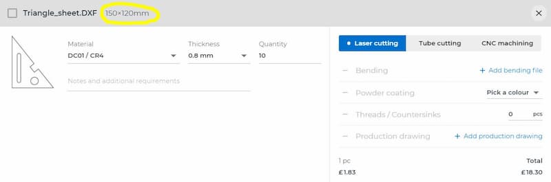
All drawings must be 1:1. Overwriting dimensions will not help. The scale command is your only tool. You can check if the dimensions are correct after uploading your drawing.
Create Your Drawing from Scratch
Save as files often bring unnecessary hidden layers or unnoticed faraway views with them. Create a new drawing instead of using an old as template.
One Part per Drawing
Cutting Lines Only
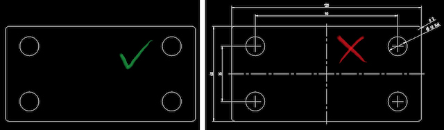
There must be nothing else in the cutting file besides the cutting lines. No title block, dimensions, tolerances, centre lines, bending lines or hatching.
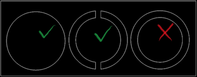
Breaking the Views
Don’t do it. The system does not recognise it and has no way of knowing the actual dimensions of the part.
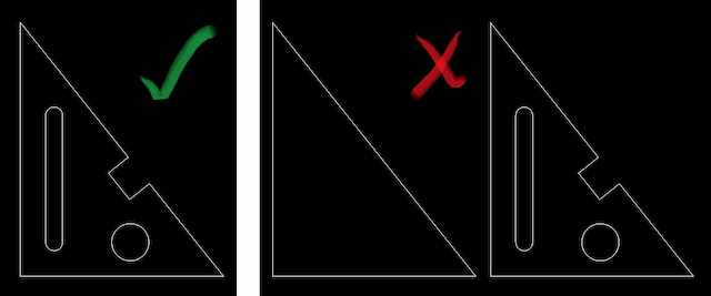
Connected Lines
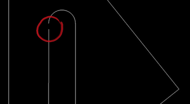
Avoid Splines
Splines can cause plenty of problems. Laser cutters have their own software that tends to interpret splines in a way that produces an unsatisfying result. Use arcs and lines instead. They are easily readable for laser cutting software.
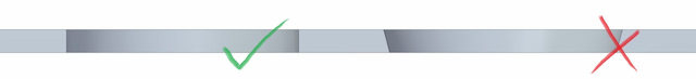
No Overlapping Lines
May be hard to notice with the human eye but the computers recognise them and calculate them as extra cuts.