

ASME Y14.5 2009 GD&T Standards lists out 14 types of geometric tolerances. These 14 tolerances are bunched up into five different groups based on the type of control they offer. Among these five groups is form control.
Form control limits the final shape’s deviation from its ideal form. And GD&T straightness is one of the tolerances to assure a feature’s closeness to the ideal.
What is Straightness (GD&T)?
Straightness tolerance is a 2-dimensional GD&T callout that controls the straightness of part features. No axis can be perfectly straight. The goal is to ensure it is straight enough for the application. This callout sets a standard on how straight a feature must be along its length.
Straightness can control two very different types of functions. It is the only callout that can control either lines on a surface or a FOS (feature of size). It may be used to control the straightness of a surface or an axis.
Also, the feature control frame is different in each case. Let’s see what we mean by either of these functions.
Surface straightness
When we apply this callout to specify surface straightness, the tolerance zone forms a total wide zone above and below the ideal surface position and controls any deviations. Surface straightness controls the form of a line anywhere on the surface and has 2 types of applications:
The first type is a flat surface such as a face of a cube.
The second type is a cylindrical surface in the axial direction.
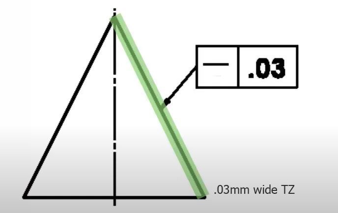
In both cases, the tolerance zone forms a 2D plane. It is shown as two parallel lines (also parallel to the surface), one above and the other below the surface.
Axis straightness
The second function that this callout can control is the straightness of an axis. The amount of linear deviation in the axis is an important feature that must be controlled for a seamless assembly. The straightness callout can be used to keep this deviation of the derived median line within permissible limits.
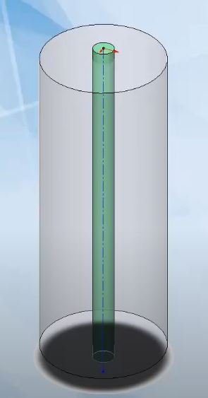
The tolerance zone, instead of applying to the surface, applies to the part’s axis in this case. Also, instead of being above and below the axis, the tolerance zone forms a cylindrical area around the centre axis.
Feature Control Frame (FCF) of Straightness
The feature control frame tells us all the necessary information about the tolerance.
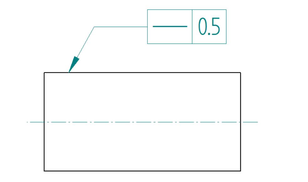
Surface straightness FCF
When controlling the surface straightness GD&T, the geometric characteristic block contains the symbol for straightness. The symbol for straightness is a short horizontal line, much like a hyphen.
The second block contains the type of tolerance zone, the tolerance value, and material modifiers (e.g. maximum material condition) if any. Since the tolerance zone type is a total wide zone, no symbols are needed as this is the default zone.
The straightness callout (as all other form controls) does not need a datum. The leader arrow only marks the surface to be controlled.
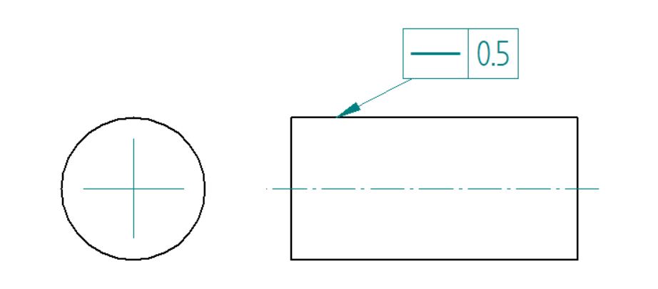
Axis straightness FCF
When it comes to axis straightness, the feature control frame remains similar for the most part, except for an added symbol for the type of tolerance zone. Since this zone is a cylinder as mentioned before, the second block contains the diameter symbol to denote the same.
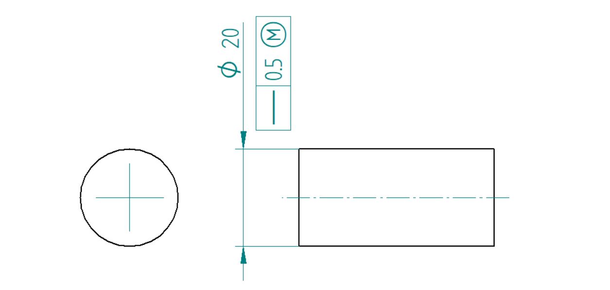
Another difference is that for axis straightness, the leader arrow, instead of marking the surface, points to the part’s diametric size dimension.
When the arrow marks a particular size dimension, the FCF is understood to be controlling the centre plane or the axis of the feature. Thus, pointing towards the part’s diametric dimension indicates that the callout controls the part’s axis.
How to Measure Straightness?

ARVE error: url: https://www.googleapis.com/youtube/v3/videos?part=snippet%2Cstatistics&id=qrFiZrf_IrY&key=AIzaSyAQ7WFzTAUrOX-FjsIrFS3JwZBFzgIvloc Status code 200 expected but was 403.
The method for measuring surface straightness and axis straightness is different. We shall look at how to inspect each type of function.
Surface straightness
Measuring surface straightness is pretty straightforward. A height gauge is secured on the specified location on the surface and moved in a straight line in the direction called out in the feature control frame.
As the gauge slides along the surface, any variations in the straightness or flatness of the surface are observed on the gauge and recorded.
Axis straightness
There are two methods available for measuring axis straightness:
Dial gauge
The first method is used when we need accurate deviations of the part axis and the number of parts is limited. This method uses dial gauges. The steps in the first method are as follows:
- Secure the part at both ends in such a way that it rotates along the axis under straightness control.
- Place two dial gauges at opposite positions of the cylinder’s curved surface. Two dial gauges work in tandem to locate the median point at that cross-section.
- At the same cross-section, the part is rotated to record measurement readings at various angles.
- Averaging multiple sets of measurements at various angles, we calculate the median point. This median point is a point on the part’s axis.
- The machinists then repeat the dimensioning and calculation procedure at multiple cross-sections and plot the part’s complete axis in 3D.
- If this axis is within the specified tolerance zone, the part is approved.
Cylinder gauge
The second method is more suitable for mass production scenarios where a large number of parts must be examined in a short time. This method also works for parts that do not need a high degree of accuracy.
It uses a cylinder gauge that is slightly larger than the cylindrical part. If the part fits into this gauge, it is approved without taking a single measurement. The testing equipment is called a go/no-go gauge.
To further limit the variation in part diameter and ensure better assembly, we call straightness tolerance at maximum material condition. This ensures that the part will always fit in a hole of a specific size.
- Personal account manager
- Quality assurance
- Payment terms for companies
- On-time delivery by Fractory
Why Use Straightness Tolerance?
Straightness comes in handy when two parts in an assembly need to have a line contact. Using straightness, we mark the mating surface so that special attention is given to it during machining.
Straightness control is used in the design and manufacture of hydraulic sleeves, tubes, and covers that need perfect contact to hold high pressures.
Axis straightness is applied in the design of pins and cylindrical parts that need to fit into bores or holes to function. Straightness callout ensures that the parts mate even at the maximum material condition.
FAQ
What is the derived median line?
The derived median line is a line formed by joining the median points at each cross-section of a part. The meridian line should match the criteria set by GD&T straightness control. If the part matches the tolerancing requirements, it passes for quality.
What is bonus tolerance?
The bonus tolerance is an additional tolerance that comes into play when the straightness callout comes with a maximum material condition (MMC) modifier. In simple terms, as a part’s actual size departs from the MMC size, the difference between the actual size and the MMC size is added to the straightness tolerance value. This is known as bonus tolerance.
For example, imagine a pin that needs to fit into a hole of a given size at MMC. Now, at MMC, the pin needs to be extremely straight or have the perfect form (as per rule no. 1 of GD&T) to ensure proper assembly. As the pin diameter becomes smaller (deviates from MMC), the restrictions on the part’s straightness are relaxed.
In other words, the part needs to be less and less straight as the pin size reduces to fit the hole. This means that pins with a barrel, waist, or concave/convex shape will still clear the go/no-go gauge designed for them as they depart from MMC.
