

An engineering drawing is a subcategory of technical drawings. The purpose is to convey all the information necessary for manufacturing a product or a part.
Engineering drawings use standardised language and symbols. This makes understanding the drawings simple with little to no personal interpretation possibilities.
So let’s look at the different line and view types you will come across in the engineering discipline.
The Purpose of Engineering Drawings
As already said, such a technical drawing has all the information for manufacturing a part or welding and building an assembly. The info includes dimensions, part names and numbers, etc. So once a manufacturing engineer gets the drawing, he can start the production process without a second thought.
First, we have to pause for a second and address our own customers here to avoid confusion. The drawings you submit for instant pricing and manufacturing in our system do not need any of this. The same applies to 3D models. CAD files and drawings made according to our design tips include all the necessary information for making your product. The only time we ask for a drawing is if you want to specify tolerances.
Still, knowing all the rules and basics of formatting is an absolute must in the industry, as traditional manufacturing companies still need detailed drawings.
How to Make Drawings?
A few decades ago, you would have had to sit down at a drawing board covered with papers of different sizes, rulers, callipers, etc. Today, all these instruments are still good for manual drafting but no contemporary manufacturer really wants such drawings.
Why? Because most of the machinery uses CNC systems that can read the information straight from the files and produce a cutting program accordingly. Drawings done by hand would just add a lot of manual work for manufacturing engineers.
So, we are left with only one option really – every engineer should use CAD (computer aided design) software because of its many advantages.
You can, of course, use CAD for making drawings from scratch. But the easier option is to first make a 3D model and create the drawings from that, as the programs generate the views with only a few clicks. All you need to do is add the dimensions. Having models also makes updating the drawings for revisions simple.
Basic Components of an Engineering Drawing
Let’s see what makes up an engineering drawing. A single drawing includes many elements with quite a few variations to each of them. So let’s take a closer look here.
Different Types of Lines
Not every line on an engineering drawing is equal. The different options make it possible to show both visible and hidden edges of a part, centre lines, etc.
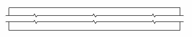
The most common is a continuous line, also known as a drawing line. This represents the physical boundaries of an object. Put simply, these lines are for drawing objects. The line thickness varies – the outer contour uses thicker lines and the inner lines are thinner.
Hidden lines can show something that would not be otherwise visible on the drawings. For example, hidden lines may show the length of an internal step in a turned part without using a section or a cutout view (we explain both later).

Centre lines are used to show holes and the symmetric properties of parts. Showing symmetricity can reduce the number of dimensions and make the drawing more eye-pleasing, thus easier to read.

Extension lines annotate what is being measured. The dimension line has two arrowheads between the extension lines and the measurement on top (or inside, like in the image above) of the line.
Break lines indicate that a view has been broken. If you have a part that is 3000 mm long and 10 mm wide with symmetric properties, using a break-out gives all the info without using as much space.
While a good way to provide information to people, CNC machines need full views to cut the parts. Otherwise, the manufacturing engineer has to reconstruct the whole part from the measurements.
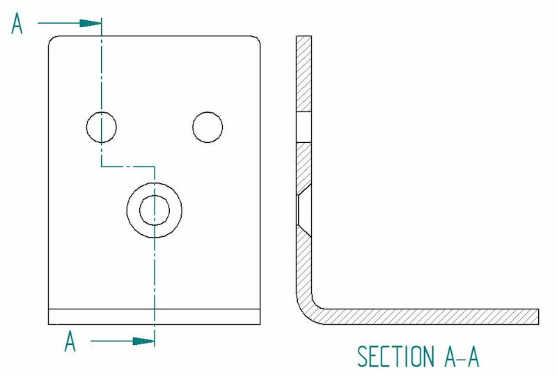
When using a cutout view, the cutting plane lines show the trajectory of the cutout. Here you can see that the A-A cutting line brings both types of holes into the view.
Types of Views
So let’s take a closer look at the different types of views that are often present in a manufacturing drawing. Each serves a certain purpose. Bear in mind that adding views should follow the same logic as dimensioning – include as little as possible and as much as necessary.
A tip for good engineering practice – only include a view if it contributes to the overall understanding of the design.
Isometric View
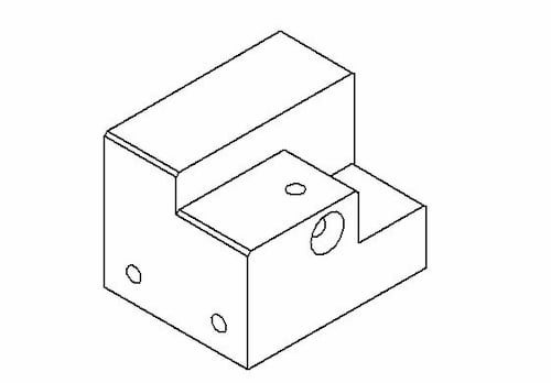
Isometric drawings show parts as three-dimensional. All the vertical lines stay vertical (compared to the front view) and otherwise, parallel lines are shown at a 30-degree angle.
The lines that are vertical and parallel are in their true length. This means you can use a ruler and the scaling of the drawing to easily measure the length straight from a paper drawing, for example. The same does not apply to angled lines.
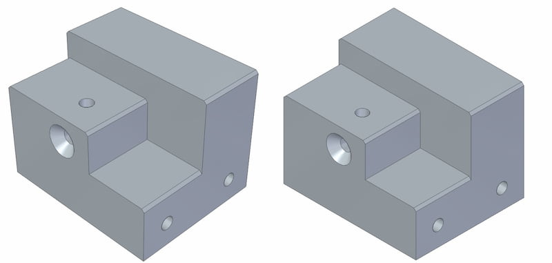
It is important to distinguish the isometric view from a perspective view. A perspective view is an artistic one that represents an object as it seems to the eye. Engineers stay true to the dimensions rather than optical illusions.
Orthographic View
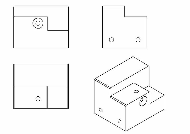
This is the bread and butter of an engineering drawing. An orthographic view or orthographic projection is a way of representing a 3D object in 2 dimensions.
Thus, a 2D view has to convey everything necessary for part production. This kind of representation allows for avoiding any kind of distortion of lengths.
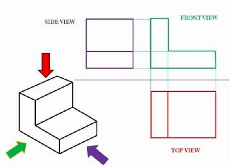
The most common way to communicate all the information is by using three different views in a multiview drawing:
- Front view
- Top view
- Side view
It may be possible that some additional views are necessary to show all the info. But again, less is more.
The positioning of the views differs a bit regionally. For example, look at the image below to compare the US and ISO layouts.
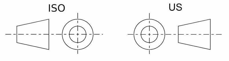
The one on the left is called first-angle projection. Here, the top view is under the front view, the right view is at the left of the front view, etc. The ISO standard is primarily used in Europe.
On the right, you can see a third-angle projection. The right view is on the right, the top view is on the top of the front view, etc. This system is especially popular in the US and Canada.
Flat Pattern
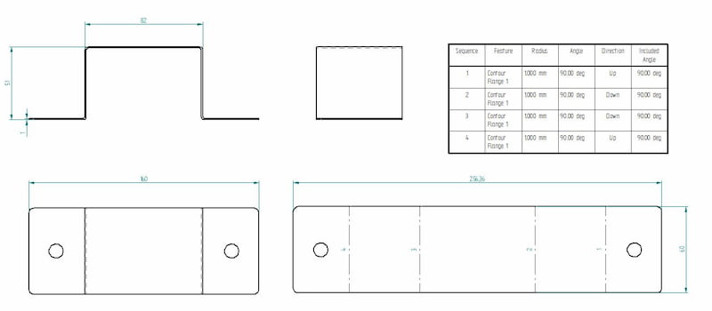
If you are making a folded sheet metal part, do not forget to add a flat pattern view. The cutting job comes before bending. When it comes to our customers, the easiest way is just to upload a STEP file without any accompanying drawings.
- Personal account manager
- Quality assurance
- Payment terms for companies
- On-time delivery by Fractory
Creating a flat pattern view is usually pretty simple. Just be aware that you are using the sheet metal environment when making sheet metal parts in CAD. There you have the option to “generate a flat pattern” which you can easily add to the main drawing.
If you are using the standard part environment, the same option is not available. Still, many CAD programs can convert a standard part into sheet metal if the part properties correspond to sheet metal (e.g. uniform thickness, inside radius, etc.).
Section View
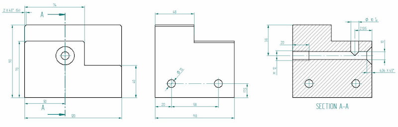
A section view can easily display some of the part features that are not evident when looking just from the outset. Cross section is the preferred option compared to hidden lines as it brings more clarity. The cross hatching feature is an indicator for cross sectional views.
Cutout View
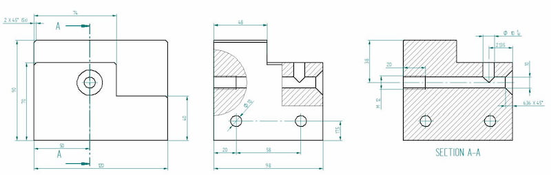
This is the same image we used for illustrating the section view. With one slight difference – the side view includes cutouts. Cutouts can reduce the number of different views on a single drawing.
Thus, we could easily delete the section view and add all the necessary dimensions to cutouts.
Detail View
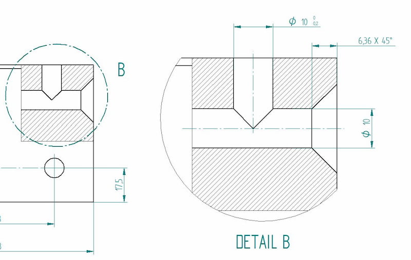
The detail view gives us a close-up of a selected section of a larger view. This can be especially useful if an otherwise large part includes many important dimensions in a small area. Using the detail view improves the readability of these measurements.
Auxiliary View
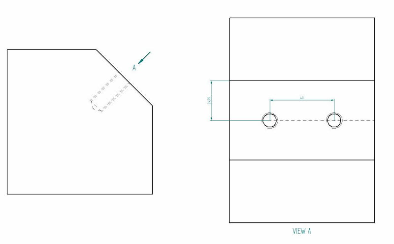
An orthographic view to represent planes that are not horizontal or vertical. It helps to show inclined surfaces without any distortion.
Dimensions
As said before, new CNC machines are actually able to read the dimensions straight from the lines. However, a traditional manufacturing drawing shows all the necessary dimensions for producing the parts.
The keyword here is necessary. Avoid using the auto-dimensioning feature that a lot of CAD programs offer because they tend to show everything they can find. For a beginner, it may seem like adding it all ensures that no mistakes can be made.
Actually, it can result in a confusing web of measurements that is left for the manufacturing engineer to untangle. Also, adding all the dimensions you can find makes it hard to pinpoint which ones are the most important.
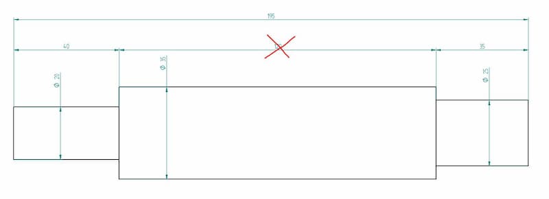
The image above shows a shaft with all the measurements. In reality, it creates a closed system whereby the manufacturer cannot guarantee all these dimensions 100%. Therefore, you have to determine the most important ones. In our case, we chose the end steps to be more important than the length of the central part. Thus, we should delete the 120 mm dimension.
One crucial bit of information that is missing from CAD models is geometric dimensioning and tolerancing (GD & T). For example, when looking to produce a shaft for a bearing system, limits and fits are of high importance. The right dimensions can guarantee a longer life with less maintenance.
While you can fetch all the dimensions automatically by clicking the measure button, adding engineering tolerances needs manual action.
Therefore, adding dimensions with lower and upper limits or fit classes is still important. Regarding Fractory’s service, we would ask you to enclose a separate drawing with these parameters. Note that you do not have to provide the whole dimensioning – only include the tolerances of a single hole on your engineering drawings if necessary.
Information Blocks
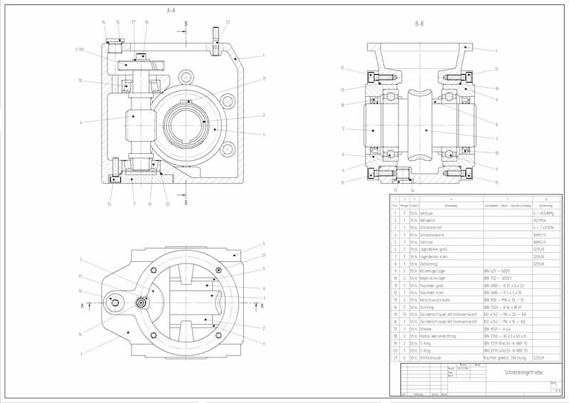
The little boxes in the bottom right corner show additional information. The title block includes the author’s name, part name, part number, quantity, coating, scale, etc. There can be much more info on there but the title blocks vary widely between different companies.
Information blocks also include a bill of materials or BOM for short. These blocks list all the components used in the assembly, along with additional information like quantities, part names, etc.
Assembly Drawings
Many engineers’ drawings make the mistake of trying to include all the information about each individual part in an assembly drawing. To avoid this, remember the purpose of these engineering drawings during the creation process – they must make the assembling easy.
Exploded views, section views, numbered parts, general dimensions, cutouts, and detail views (or close-ups) are all tools you can use to achieve this goal.
It should be clear where each part goes and how it is attached – whether it needs assembly welding, bolted connections, riveting or something else. The bill of materials is there to help you, so make sure the information available there is correct regarding part numbers, names and quantities.
Keeping everything above in mind will help you create assembly drawings that make life easier on the shop floor. A piece of great advice I once received goes like this – keep the thinking in the drawing room. Avoiding multiple interpretation possibilities at later steps will significantly decrease the number of errors.
ARVE error: url: https://www.googleapis.com/youtube/v3/videos?part=snippet%2Cstatistics&id=32CXeJVgiLA&key=AIzaSyAQ7WFzTAUrOX-FjsIrFS3JwZBFzgIvloc Status code 200 expected but was 403.
What Does the Future Hold?
Engineering drawings are still a big part of an engineer’s job. All in all, making them contributes to about 20% of a design engineer’s work time.
We at Fractory are trying to save this time by automating the reading of 3D models for production, be it for different cutting and bending operations or CNC machining. This leaves engineers with the task of producing assembly and GD&T drawings only. The purpose is to keep the focus on engineering better products.
The engineering community is seeing this movement as a new trend. But as we all know, taking the whole industry up to a new standard takes a lot of time. Thus, if you still outsource your production to manufacturing companies that need drawings, you must know the basics at the very least.
Leaving room for interpretation creates a situation where your idea may not be executed as planned. And there is nobody else to blame but the author.
So consider this stage of the product development process as an integral part that requires thinking along. Keep the thinking in the drawing room.
