

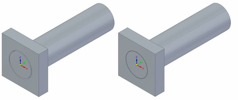
In engineering, a fit refers to the clearance between two mating parts. The choice of an engineering fit determines whether the two parts can move relative to each other in case of a clearance fit, or act as a whole in case of a tight interference fit.
While limits and fits apply to all sorts of mating parts, their main use is for regulating the sizes of mating shafts and holes for best performance.
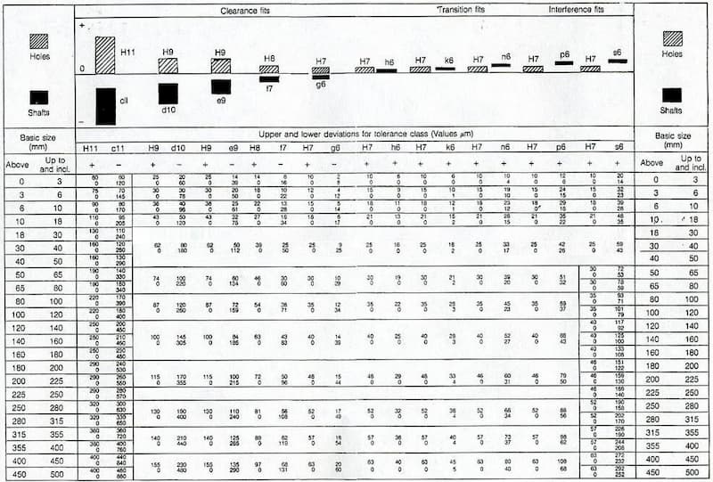
Both ISO and ANSI have standardised fits in three classes – clearance, transition and interference. Each class has a variety of options available for choosing the correct one for a specific application.
Tolerance Grade
With engineering fits, the tolerance will always be shown in an alpha-numeric code. For example, a hole tolerance may be H7. The capital letter signifies that we are dealing with a hole. When indicating tolerance for a shaft, the letter will be lowercase.
The number shows the international tolerance grade (ISO 286). A tolerance class determines a range of values that the final measurement can vary from the base measurement.
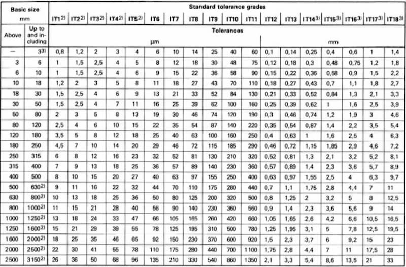
From the table, we can see that the tolerance grade applies to a range of basic sizes. So if we have a hole with a nominal size of 25 mm and a tolerance class of H7, we will fit into the 18…30 mm basic size group. Looking at the IT7 tolerance grade, the chart gives an allowed variance of 0.021 mm.
The letter signifies the start of the tolerance zone. For H7, the starting point is at exactly 25.000 mm. The maximum hole size is then 25.021 mm. For F7, the tolerance range is the same, but the starting point is 25.020 mm, taking the last acceptable measurement to 25.041 mm.
A great way to find all the corresponding engineering tolerances to specific measurements is by using a limits & fits calculator.
Hole and Shaft Basis System
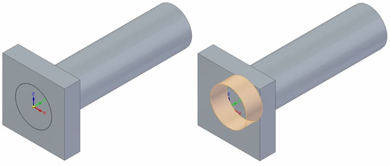
When choosing a system for a fit, you have 2 options – hole and shaft system. The system tells which part has a controlled measurement and which part is made based on the other.
In short, the hole-based system uses a constant measurement for the hole and the diameter of the shaft is made accordingly to achieve the required fit.
And the shaft-based system works vice versa.
Engineers tend to follow the hole system because of simplicity. As the hole size stays constant, the shaft’s upper and lower deviation values determine the type of fit. Drilling does not allow for much precision, as the tooling comes in certain measurements.
At the same time, CNC turning services are able to create shafts with exact measurements, so achieving the desired fit is just easier this way.
Limits & Fits

In engineering, we have to define the tolerances of parts to ensure a long lifespan and proper working of a machine. We can choose the fits according to the necessities and working conditions. The three main categories are:
- Clearance fit
- Transition fit
- Interference fit
All these come with another subset of categories, each designed for different circumstances. Of course, we have to keep in mind that closer tolerances and more snug fits will result in higher costs because of higher demands on machining accuracy and the difficulty of assembly.
A clearance fit always leaves room between the two parts. A transition fit is somewhere in between clearance fits and interference fits and can end up either way but without leaving much room nor being too tight. An interference fit is tight and creating the fit requires considerable force and other techniques for easing the process.
- Personal account manager
- Quality assurance
- Payment terms for companies
- On-time delivery by Fractory
Clearance Fits
With a clearance fit, the shaft is always smaller than the hole. This enables easy assembly and leaves room for sliding and rotational movement.
When the shaft diameter is at its minimum and hole diameter at its maximum, we have a situation of maximum clearance. When the shaft diameter is at its maximum and hole diameter at its minimum, we have a situation of minimum clearance.
Clearance fits come in 6 sub-categories. Starting from the loosest:
- Loose running
- Free running
- Close running
- Sliding
- Close clearance
- Locational clearance
Loose Running Fit
Fit with the largest clearance. Suitable for applications where accuracy is not of the utmost importance and contamination may be a problem.
Example uses in engineering: Fits exposed to dust contamination, corrosion, thermal and mechanical deformations. Pivots, latches, etc.
Example fits: H11/c11, H11/a11, H11/d11 (all hole-basis), C11/h11, A11/h11, D11/h11 (all shaft-basis)
Using a 25 mm diameter, a H11/c11 fit gives a minimum clearance of 0.11 mm and a maximum clearance of 0.37 mm. In this case, the shaft diameter can fall in between 24.76 and 24.89 mm while the minimum hole size is 25 mm and the max 25.13 mm.
Free Running Fit
Suitable where no special requirements apply to the accuracy of matching parts. Leaves room for movement in environments with heavy temperature fluctuations, high running speeds and heavy plain bearing pressures.
Example uses in engineering: Applications where maintaining a film of oil lubrication is important. For example, shaft and plain bearing fits with little rotational movement.
Example fits: H9/d9, H9/c9, H9/d10 (all hole-basis), D9/h9, D9/h8, D10/h9 (all shaft-basis)
Using a 25 mm diameter, a H9/d9 fit gives a minimum clearance of 0.065 mm and a max clearance of 0.169 mm.
Close Running Fit
Close-running fits are a good choice for applications that require smaller clearances and moderate accuracy. Good for withstanding medium speeds and pressures.
Example uses in engineering: Machine tools, sliding rods, machine tool spindles, etc.
Example fits: H8/f8, H9/f8, H7/f7 (all hole-basis), F8/h6, F8/h7 (all shaft-basis)
Using a 25 mm diameter, a H8/f7 fit gives a minimum clearance of 0.020 mm and a max clearance of 0.074 mm.
Sliding Fit
Leaves a small clearance for high accuracy while maintaining ease of assembly. Parts will turn and slide quite freely.
Example uses in engineering: Guiding of shafts, sliding gears, slide valves, automobile assemblies, clutch discs, parts of machine tools, etc.
Example fits: H7/g6, H8/g7 (all hole-basis), G7/h6 (shaft-basis)
Using a 25 mm diameter, a H7/g6 fit gives a minimum clearance of 0.007 mm and a max clearance of 0.041 mm.
Locational Clearance Fit
Location clearance fits provide minimal clearance for high-accuracy requirements. The assembly does not need any force and the mating parts can turn and slide freely with lubrication, helping with assembly by hand. Provides a snug fit for stationary parts.
Example uses in engineering: Roller guides, guiding of shafts, etc.
Example fits: H7/h6, H8/h7, H8/h9, H8/h8 (all hole-basis)
Using a 25 mm diameter, a H7/h6 fit gives a minimum clearance of 0.000 mm and a max clearance of 0.034 mm.
Transition Fits
A transition fit encompasses two possibilities. The shaft may be a little bigger than the hole, requiring some force to create the fit. At the other end of the spectrum is a clearance fit with a little bit of room for movement.
Specifying a transition fit means that both outcomes are possible even inside a single batch.
Transition fits come in 2 forms – similar fit and fixed fit.
Similar Fit
Leaves a small clearance or creates a small interference. Assembly is possible using a rubber mallet.
Example uses: Hubs, gears, pulleys, bearings, etc.
Example fits: H7/k6 for hole-basis and K7/h6 for shaft-basis
Using a 25 mm diameter, a H7/k6 fit gives a max clearance of 0.019 mm and a max interference of 0.015 mm.
Fixed Fit
Leaves a small clearance or creates a small interference. Assembly is possible using light force.
Example uses in engineering: Driven bushes, armatures on shafts, etc.
Example fits: H7/n6 for hole-basis and N7/h6 for shaft-basis
Using a 25 mm diameter, a H7/n6 fit gives a max clearance of 0.006 mm and a max interference of 0.028 mm.
Interference Fits
Interference fits are also known as press fits or friction fits. These types of fits always have the same principle of having a larger shaft compared to the hole size.
The assembly stage requires force, sometimes lubrication, heating of the hole and freezing of the shaft. These help to increase/decrease the hole and shaft sizes, respectively, to make for an easier process.
The interference helps to secure the relative positioning of the shaft and hub even during rotation, making this type of fit good for transmitting rotational speed and power.
Press Fit
Minimal interference. Assembly can be performed with cold pressing.
Example uses in engineering: Hubs, bushings, bearings, etc.
Example fits: H7/p6 for hole-basis, P7/h6 for shaft-basis
Using a 25 mm diameter, a H7/p6 fit gives a min interference of 0.001 mm and a max interference of 0.035 mm.
Driving Fit
Needs higher assembly forces for cold pressing. Another way is by using hot pressing. This interference fit is more prominent than with a press fit.
Example uses in engineering: Permanent mounting of gears, shafts, bushes, etc.
Example fits: H7/s6 for hole-basis, S7/h6 for shaft-basis
Using a 25 mm diameter, a H7/s6 fit gives a min interference of 0.014 mm and a max interference of 0.048 mm.
Forced Fit
High interference fit. Assembly requires heating the part with a hole and freezing of the shaft to force the mating parts together. Disassembly can result in broken parts.
Example uses in engineering: Shafts, gears, etc.
Example fits: H7/u6 for hole-basis, U7/h6 for shaft-basis
Using a 25 mm diameter, a H7/u6 fit gives a min interference of 0.027 mm and a max interference of 0.061 mm.
