


Gears are rotating machine elements that transmit torque from one shaft to another via the teeth machined into them. Gears with similar tooth profiles mesh. This allows transmitting the power from a driving shaft to a driven one.
Different gear types are used in machines as they can be designed for a range of forces from a range of materials. They can also be used to increase/decrease rotational velocity as well as change the direction of rotation.
Gears can also be used to pump liquids as in the case of gear pumps for fuel oil and lubrication oil for instance. They mesh so well (forming a positive displacement pump) that the liquid is pushed ahead with high delivery pressures.
They are also used in chain blocks to lift heavy objects easily. Thus, gears are a core component of most equipment as they are quite versatile and able to perform a variety of tasks.
Difference Between Gears & Sprockets
Gears and sprockets both use teeth to transfer torque. While at the outset, they both are similar-looking components, there are some marked differences that can help us identify them with ease.
- Gears are the preferred solution for short-distance transmissions. Using a sprocket and a chain helps to transmit the power over a considerably longer distance, using a chain.
- While the teeth of two gears mesh perfectly with each other, it is not so for a sprocket. A sprocket tooth is actually designed to fit into a cavity such as the chain of a bicycle or the tracks of a military tank.
- While gears are capable of transmitting torque in parallel, perpendicular, and any other orientation in between, sprockets can only do so along the parallel axis.
- Gears transfer torque in the opposite direction. If the driving shaft is rotating clockwise, the driven shaft will rotate anticlockwise. With sprockets, the rotational direction remains the same.
- Gears with a broken tooth may not be as effective as a perfect system but they will work. In case of sprockets, one or more broken teeth can cause the chain to leave its position and the system will come to a halt.
Different Types of Gears and Their Uses
There are many types of gears and each one offers some trade-offs. It comes down to what expectations a designer has from a gear train. The factors that may be considered are as follows:
- Torque/duty cycle needs
- Rotation speed/gear ratio
- Service environment
- Space availability/restrictions
- Budget
Based on these factors, the selection is further narrowed down to whether the gears will be operating on parallel/non-parallel and intersecting/non-intersecting axes. Let’s learn a little more about what choices one has and what each one of them offers.
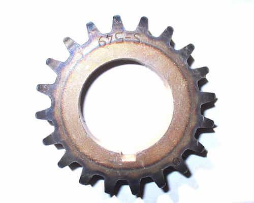
Spur Gear
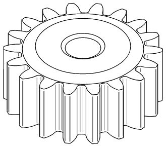
The most common type of gear used. Its simple and effective design creates a possibility for a wide range of applications. The teeth on spur gears are parallel and straight-cut on a cylindrical gear body.
Spur gears use the parallel axes configuration in mated pairs. They work great for moderate load and moderate speed applications and are generally used in applications where noise and vibration are not a concern.
Two differently sized spur gears can be used to change torque and RPM. The simple design allows for a high degree of manufacturing precision. One of its advantages is providing high transmission efficiency while not causing axial loading of the shaft.
Some disadvantages include high noise and vibration in high-speed applications and the great amount of stress the teeth are subjected to in this simple design. This limits its loading capacity.
- Personal account manager
- Quality assurance
- Payment terms for companies
- On-time delivery by Fractory
Gear Rack
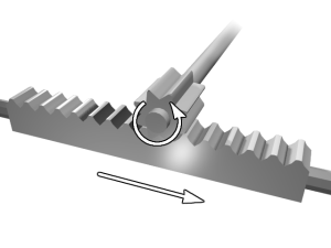
It is possible to combine spur gears with a rack to convert rotational motion to linear motion. A rack consists of teeth cut in a straight row on a flat surface. These teeth have the same profile as the spur gear.
The spur gear teeth mate with the teeth on the rack similar to how they would mesh with another spur gear. When the gear rotates, it pushes the rack in a straight line.
The gear rack system, also known as rack and pinion system, finds use in many products such as automobiles, stairlifts, railways etc. It is used to fine-tune machinery parameters to, for example, control the amount of fuel that enters a diesel generator through a high-pressure fuel pump.
Internal Gear
Spur gears may also be combined with an internal gear to create a planetary gear system. An internal gear has teeth on the inside of an annulus-shaped gear body. This gear mates with spur gears placed inside it to transfer motion.
Internal gear mechanisms are of three types: planetary, solar, and star. Depending on the application and other pertinent factors, a variety of speed transmission ratios may be produced along with the desired rotational direction.
Internal gears are employed in a variety of industries where they are commonly used as reduction gears. They are perfect for changing gear ratios in bicycles, watches, and automatic transmission in cars.
Helical Gear
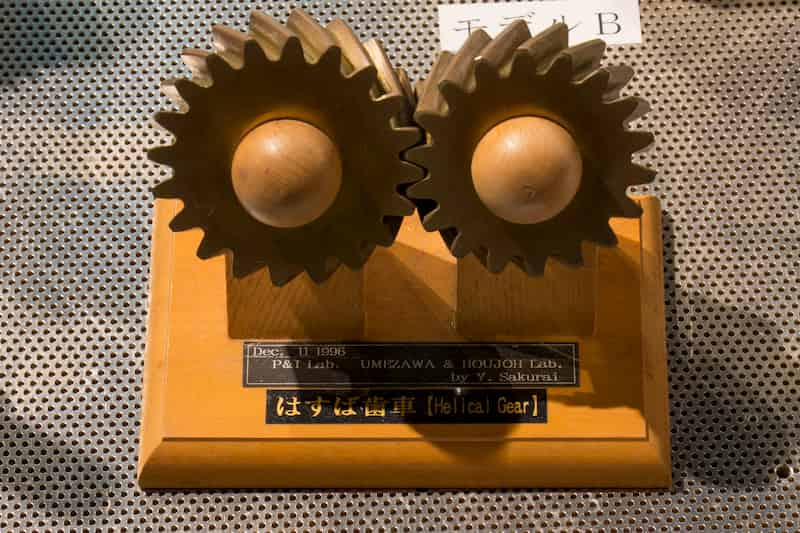
Helical gears are similar to spur gears in construction and application as they use the same parallel axes configuration with parallel teeth. The teeth, however, are angled such a way that if we were to extend them, they would form a helix around the shaft, hence the name.
Unlike spur gears, helical gear teeth come in contact gradually with each other. This avoids impact loading of teeth. Due to this feature of gradual loading, more than one tooth pair are in contact at a time. Load sharing takes place, allowing helical gears to sustain higher loads compared to spur gears.
The gradual loading also reduces noise and vibration, making this type ideal for high loads and high-speed applications.
Use of helical gears produces axial loads and hence they need to be supported by thrust bearings. A pair of mating helical gears consists of one left-hand twist and one right-hand twist gear, unlike spur gears where the teeth are always parallel with the axis.
Double Helical Gear
Double helical gears are a special type of helical gear. They were created to overcome the high axial thrust associated with single helical gears.
Double helical gears combine two opposite orientations of teeth together, usually along the middle of the gear face. The axial thrust produced by the left-hand tooth is nullified by the right-hand tooth, thus eliminating the need for a thrust bearing.
Typical use-cases for double helical gears include prime movers such as gas turbines and generators. They also find use in fans, pumps, and compressors.
As in the case of single helical gears, double helical gears also provide smooth and silent operation at all speeds.
Herringbone Gear
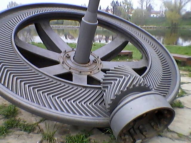
Herringbone gear is a special type of double helical gear. Whereas the helical gear has a groove in the middle between the teeth, the herringbone gear does not.
Such a design helps to cancel out the axial forces on each set of teeth. Thus, larger angles are allowed as there is less danger of failure.
It normally uses the intersecting axes configuration where the two shafts are perpendicular to each other. The power is transmitted from the herringbone gear to a regular double helical gear.
Herringbone gear does not produce any axial thrust and ensures a quieter, smoother, and effective operation at all speeds and loads.
Screw Gear
Screw gear is also known as crossed helical gear. They are used for motion transmission between non-parallel non-intersecting shafts.
While helical gears usually engage between parallel shafts, screw gears do so at 90 degrees.
The teeth on a screw gear are in the form of a helix. They form a point of contact between two gears and hence are not very suitable for high load and high-speed applications. They also have low efficiency compared to other helical gears.
A unique trait of screw gears is that they use the same hand pair when engaging. Motion is transmitted as the same hand pairs slide against each other. Lubrication of screw gears is therefore a necessity. There are no limitations on the combination of the number of teeth.
Bevel Gear

The types of gear we call bevel are cone-shaped, placing the teeth on the conical surface. The cone top is lopped off. The two mating gears are generally placed on perpendicular intersecting shaft axes.
One of the most common uses for bevel gears is for changing the power transmission axis. While doing so, RPM and torque may be changed as necessary by varying the gear size.
There is also the option to increase or decrease the angle between the shafts. The two shafts need not be exactly perpendicular.
Due to the design of bevel gear, when two mating teeth come in contact, the contact takes place all at once instead of gradually. Thus, a similar problem of high stress as in the case of spur gears occurs.
This high impact mating produces more noise and causes excessive stress on the gear tooth. The high stress ultimately affects the durability and service life of the bevel gear.
It also affects the sort of applications they are used for. Straight bevel gears are generally used at low RPM (less than 500 RPM or 2 m/s circumferential speed).
Despite these limitations, they find use in many different industries. Some of the equipment that uses bevel gears are automobiles, pumps, machine tools (milling and turning), gardening equipment, fluid control valves, and food packaging equipment. They are also the easiest to manufacture and hence, are quite affordable and available in a variety of sizes.
Spiral Bevel Gear
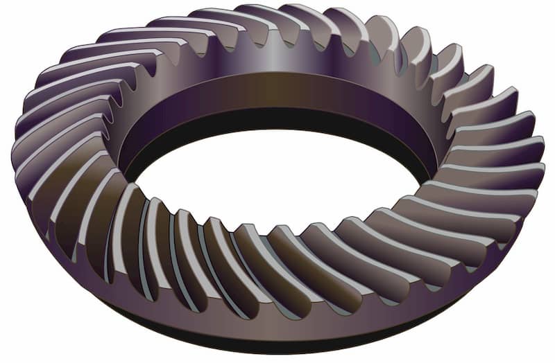
Spiral bevel gears are used to overcome the limitations of straight bevel gears. As the name suggests, the teeth on a spiral bevel gear are arranged in the form of a spiral.
When two spiral gears come in contact, they do so gradually. This avoids impact loading of the teeth as the previous gear teeth pair (that are now losing contact) are still carrying some of the load. From this pair, the new mating pair assumes the load slowly.
This makes the operation smooth and quiet. It also increases the safe loading capacity of the gear. Thus, spiral bevel gears find use in highly demanding applications (speeds greater than 500 RPM) for safe and reliable operation.
Some of these applications are power transmission, car differentials, robotics, bow and stern thrusters in ships.
Mitre Gear
Mitre gears are bevel gears with a speed ratio of 1:1. An engaging pair will always have the same number of teeth. They transmit power between intersecting axes.
Mitre gears are used in machines to change the direction of rotation only. They do not cause a change in the shaft speed or torque.
A mitre gear may be of straight or spiral type. Straight mitre gears offer the advantage of not having to deal with any axial thrust. But they come with the limitations of straight bevel gears. Spiral mitre gears produce axial thrust necessitating the need for thrust bearings.
Mitre gears usually engage at 90 degrees. But they may be produced to mate at other angles as well. If they mate at any other angle between 0 and 180, they are known as angular mitre gears. Most common range for angular mitre gears is between 45 and 120 degrees.
Hypoid Gear

Hypoid gear resembles a spiral bevel gear but there are some marked differences. Unlike spiral gears, hypoid gear shafts do not intersect.
The hypoid gear is placed offset to the crown wheel which is usually a spiral bevel gear. This positioning of the hypoid gear results in greater contact when mating. This improves load-carrying capacity as well as the durability of the transmission system.
Another difference is the shape of the hypoid gear. The gear body is in the shape of a revolved hyperboloid.
A cone forms when a right-angled triangle revolves around one of the edges that form the right angle. If we replace the hypotenuse (which is a straight line) of the right-angled triangle with a hyperbola and revolve it around the same edge, we get the hyperboloid shape.
This shape matches perfectly without any interference with the spiral bevel gear as the two mating gears are placed a little to the side.
Compared to bevel gears, hypoid gears achieve higher speed reduction due to their large contact ratio. The increased contact also permits higher load transmission while suppressing noise and vibration.
The meshing is, however, complex and the production is also difficult. Hypoid gears are used in automotive differential systems.
Hypoid gears bear some similarity to worm gear systems but they have certain advantages over them. Firstly, less sliding occurs, reducing power consumption. Secondly, the offset between the two gears is less which saves space. Finally, both gears can be heat-treated which imparts higher rigidity reducing the size of gears used.
Worm Gear
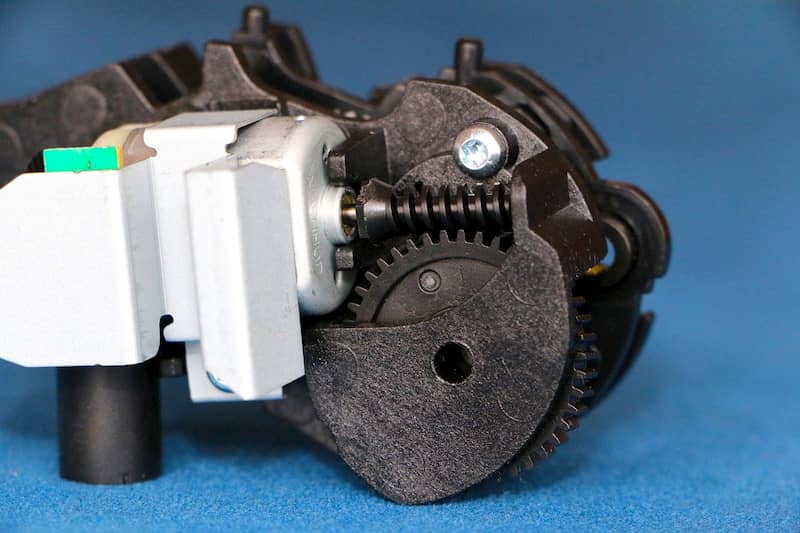
In a worm gear drive, a worm engages with a worm wheel and motion transfer takes place. A worm gear resembles a screw and as it rotates it meshes with a cylindrical gear, sometimes also known as worm wheel.
This system is used to transfer motion between two non-parallel, non-intersecting shafts. Worm gears offer one of the highest gear reduction ratios.
A unique characteristic of this gear drive is that the gear pair rotation can be locked. This is because the worm wheel cannot turn the worm gear if it is set at a certain angle. However, the worm gear can turn the worm wheel at any angle. This property is utilized in applications that require self-locking mechanisms.
Worm gears come with certain disadvantages though. The transmission efficiency is not as good compared to other gears. Also, the fact that sliding occurs between the worm and worm wheel during transmission makes lubrication a factor to pay attention to. Continuous lubrication is the basis for smooth operation.
Worm gears are common in automobiles, steering systems, lifts, and material handling systems.
Gear Parameters
Now that we have a general idea of the different types of gears, we are in a better position to get a bit technical and understand the meaning of various terms that one may come across while learning about gears.
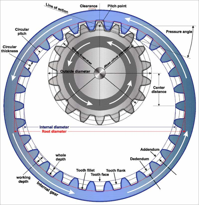
Outer Diameter
This is the maximum diameter of a gear. It is the distance from the gear body centre to the tooth tip. The outer diameter signifies the outermost extent of a gear.
Pitch Circle
The pitch circle of two engaging gears touch each other at the point where the mating teeth come in contact with each other. It runs roughly around the centre of the gear tooth. Pitch circle is where the motion transfer takes place and hence, this circle is used for all calculation purposes. The point at which the gears touch is known as pitch point.
Centre Distance
It is the distance between the centres of two mating gears of a system. It is important that this distance is set properly for effective transfer of torque. It is calculated by adding the pitch circle diameter of the two gears and dividing by two.
Root
Root is the point where the tooth connects to the gear body. It is the trough between the bottom-most part of two adjacent gear teeth.
Root diameter is the distance between the centre of a gear body and the base of a gear tooth. The tooth height of two mating gears must be cut in a way that it does not exceed the root of the gear to prevent contact of tooth tip with the other gear’s root during rotation.
Pitch
Pitch is defined as the distance between the same point on two adjacent gear teeth. It can be calculated easily by dividing the circumference of the gear at that point by the number of teeth.
But the word ‘pitch’ can be confusing as at different points along the tooth height, the value will be different. Thus, the diameter needs to be specified. Some popular pitches are circular pitch, normal base pitch, and angular pitch. Circular pitch is the distance between the same points on two teeth faces along the pitch circle.
Diametral Pitch
Diametral pitch informs us of tooth density. It is calculated by dividing the total number of gear teeth by the pitch circle diameter. Its unit is the number of teeth per meter.
Tooth Profile
Tooth profile refers to the shape of a gear tooth. There are many different options we can choose from. We could make them rectangular, triangular, in the shape of a circular arc, or move on to more complex shapes such as a parabola or an involute.
Simple shapes such as rectangles and triangles, however, create high vibration, noise, and would be very inefficient due to excessive sliding. Complex shapes improve efficiency and enable quiet operation. Let’s see what types of profiles are in use today.
Involute Tooth Profile
It is the most widely used tooth profile. There are certain advantages of using involute gears, such as:
• Easy and inexpensive to manufacture
• Can accommodate small deviations in the centre distance.
• High root thickness imparts strength
• Constant pressure angle during operation makes operation smooth
Cycloidal Tooth Profile
The cycloidal tooth profile is the second most common profile in use. This profile ensures the same wear occurs on the entire tooth. Cycloidal gear teeth find use in watches and instruments. It is seldom used for intensive applications as it is difficult to produce.
Arc of Circle Profile
This profile is not as popular but it has the advantage of slow wear as the arc is uneven. It is classified into two types: single arc and compound arc.
As the name suggests, the tooth has a cylindrical shape which mates with the other gear. Sometimes, a convex arc may fit into a concave arc for better transmission. This profile, however, is difficult to produce compared to the involute profile.
Gear Materials and Surface Treatment
Gears are produced using a variety of material and this selection will also affect the surface treatment method that may be chosen to improve performance.
Gears may be produced from different types of metals as well as non-metals such as steel, cast iron, plastic, nylon, and fibre. Each material has its own salient features:
- Steel is used for intensive applications. It provides high strength and hardness. Carbon and alloy steel are common choices.
- Cast iron is easy to produce and is generally preferred when gears are to be mass-produced. Precision is, however, lost in this type of production.
- Nylon is an inexpensive, lightweight and non-corrosive option as a gear material. Nylon is a good choice for low load, corrosion-prone applications.
Surface treatment of gears is usually necessary before putting them into service. Two useful techniques for gear surface finishing are grinding and heat treatment.
Grinding gear teeth makes them smooth and leads to quiet operation. It does increase the final cost of production though.
Many heat treatment techniques are available for improving the strength, surface finish, and durability of gears. Some of these procedures are carburising, annealing, tempering, surface hardening, and normalising.
Depending on the material used and procedure employed, the gears can be made strong, heat-resistant, hard, and durable.
