

Bending is one of the most common sheet metal fabrication operations. Also known as press braking, flanging, die bending, folding and edging, this method is used to deform a material to an angular shape.
This is done through the application of force on a workpiece. The force must exceed the material’s yield strength to achieve plastic deformation. Only then can you get a lasting result in the form of a bend.
What are the most common bending methods? How does springback affect bending? What is the k factor? How to calculate bend allowance?
All those questions are discussed in this post along with some bending tips.
We have also written another important post about press brake tooling. Knowing the tools helps you to engineer products that can be manufactured.
Bending Methods
There are quite a few different bending methods available. Each has its own advantages. The dilemma is usually between going for accuracy or simplicity, while the latter gets more usage. Simpler methods are more flexible and most importantly, need fewer different tools for getting a result.
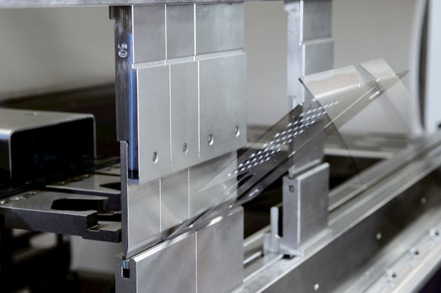
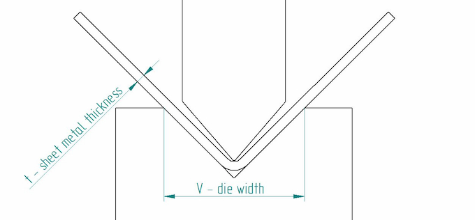
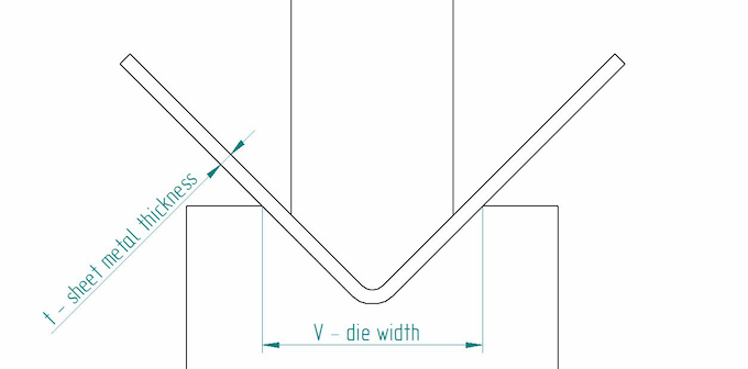
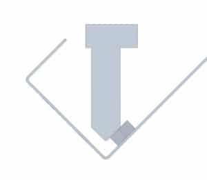
V-Bending
V-bending is the most common bending method using a punch and die. It has three subgroups – bottoming, air bending and coining. Air bending and bottoming account for around 90% of all bending jobs.
The bending force table below helps you identify the minimum flange length b (mm) and inside radii ir (mm) according to material thickness t (mm). You can also see the die width V (mm) that is needed for such specifications. Each operation needs a certain tonnage per meter. This is also shown in the table. You can see that thicker materials and smaller inside radii require more force or tonnage. The highlighted options are recommended specifications for metal bending.
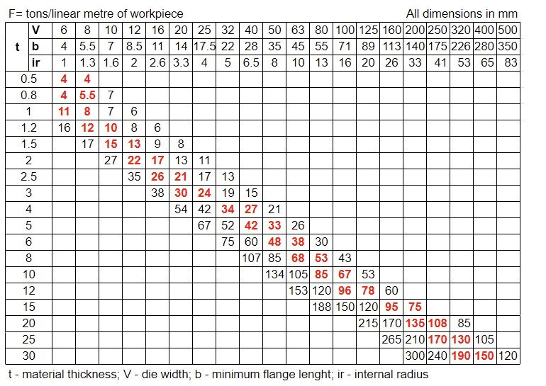
Let’s say I have a 2 mm thick sheet and I want to bend it. To keep it simple, I also use a 2 mm inside radius. I can now see that the minimum flange length is 8.5 mm for such a bend, so I have to keep it in mind when designing. The required die width is 12 mm and tonnage per meter is 22. The lowest common bench capacity is around 100 tonnes. My workpiece’s bending line is 3 m, so the overall needed force is 3*22=66 tonnes. Therefore, even a simple bench with enough room to bend 3 m pieces will do the job.
Still, there is one thing to keep in mind. This table applies to construction steels with a yield strength of around 400 MPa. When you want to bend aluminium, the tonnage value can be divided by 2, as it needs less force. The opposite happens with stainless steel – the required force is 1.7x higher than the ones displayed in this table.
Bottoming
Bottoming is also known as bottom pressing or bottom striking. As the name “bottom pressing” suggests, the punch presses the metal sheet onto the surface of the die, so the die’s angle determines the final angle of the workpiece. With bottoming, the inner radius of the angled sheet depends on the die’s radius.
As the inner line gets compressed, it needs more and more force to further manipulate it. Bottoming makes exerting this force possible, as the final angle is preset. The possibility to use more force lessens the springback effect and provides good precision.
When bottoming, an important step is calculating the V-die opening.
| Opening Width V (mm) | ||||
| Method/Thickness (mm) | 0.5…2.6 | 2.7…8 | 8.1…10 | Over 10 |
| Bottoming | 6t | 8t | 10t | 12t |
| Air bending | 12…15t | |||
| Coining | 5t | |||
The inner radius has been experimentally proven to be around 1/6 of the opening width, meaning the equation looks like this: ir=V/6.
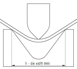
Air Bending
Partial bending, or air bending, derives its name from the fact that the working piece does not actually touch the tooling parts entirely. In partial bending, the workpiece rests on 2 points and the punch pushes the bend. Is still usually done with a press brake but there is no actual need for a sided die.
Air bending gives much flexibility. Let’s say you have a 90° die and punch. With this method, you can get a result anywhere between 90 and 180 degrees. Though less accurate than bottoming or coining, this kind of simplicity is the beauty of the method. In case the load is released and the material’s springback results in a wrong angle, it is simple to adjust by just applying some more pressure.
Of course, this is a result of lessened accuracy compared to bottoming. At the same time, partial bending’s big advantage is that no retooling is necessary for different angle bends.
- Personal account manager
- Quality assurance
- Payment terms for companies
- On-time delivery by Fractory
Coining
Coining used to be far more widely spread. It was pretty much the only way to get accurate results. Today, machinery is so well-controllable and precise, that such methods are not widely used anymore.
Coining derives it name from coins, as they have to be identical to make fake money distinguishable from the real one. Coining, in bending, gives similarly precise results. For instance, if you want to get a 45-degree angle, you need a punch and a die with the exact same angle. There is no springback to worry about.
Why? Because the die penetrates into the sheet, pressing a dent into the workpiece. This, along with the high forces used (about 5-8 times as much as in partial bending), guarantees high precision. The penetrating effect also ensures a very small inside radius for the bend.
U-Bending
ARVE error: url: https://www.googleapis.com/youtube/v3/videos?part=snippet%2Cstatistics&id=WNTi4akdNKo&key=AIzaSyAQ7WFzTAUrOX-FjsIrFS3JwZBFzgIvloc Status code 200 expected but was 403.
U-bending is in principle very similar to V-bending. There is a die and a punch, this time they are both U-shaped, resulting in a similar bend. This is a very straightforward way for bending steel U-channels, for example, but not so common as such profiles can also be produced using other more flexible methods.
Step Bending
Step bending is, in essence, repetitive V-bending. Also called bump bending, this method uses many V-bends in succession to get a large radius for your workpiece. The final quality depends on the number of bends and the step between them. The more you have them, the smoother the outcome.
ARVE error: url: https://www.googleapis.com/youtube/v3/videos?part=snippet%2Cstatistics&id=l43i4ok1RLc&key=AIzaSyAQ7WFzTAUrOX-FjsIrFS3JwZBFzgIvloc Status code 200 expected but was 403.
Bump bending is used in many cases. Some examples include conical hoppers and snowploughs. It makes large-radius bending possible with regular tools. The easier setup makes for a cheaper price, especially with small batches.
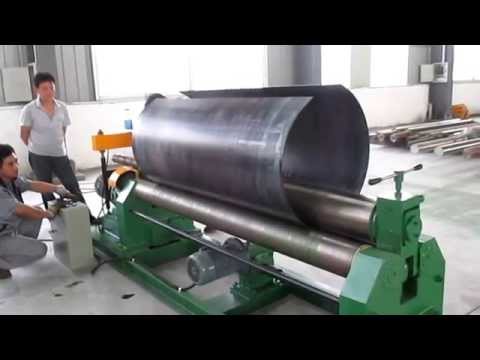
Roll Bending
Roll bending is used for making tubes or cones in different shapes. Can also be used for making large radius bends, if needed. Depending on the machine’s capacity and the number of rolls, one or more bends can be done simultaneously.
ARVE error: url: https://www.googleapis.com/youtube/v3/videos?part=snippet%2Cstatistics&id=BqdKr59T7Xc&key=AIzaSyAQ7WFzTAUrOX-FjsIrFS3JwZBFzgIvloc Status code 200 expected but was 403.
In the process, there are two driving rolls and a third adjustable one. This one moves along via frictional forces. If the part needs to be bent at both ends as well as the mid-section, an extra operation is required. This is done on a hydraulic press or press brake. Otherwise, the edges of the detail will end up flat.
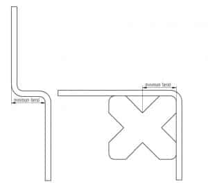
Wipe Bending
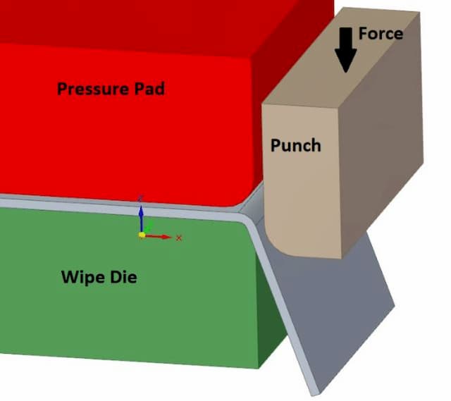
Wipe bending or edge bending, is another way to bend sheet metal edges. It is important to make sure that the sheet is properly pushed onto the wipe die. As a result, the wipe die also determines the bend’s inner radius. The slack between the wipe die and the punch plays an important role in getting a good result.
Rotary Bending
ARVE error: url: https://www.googleapis.com/youtube/v3/videos?part=snippet%2Cstatistics&id=3lBiryXJ-eQ&key=AIzaSyAQ7WFzTAUrOX-FjsIrFS3JwZBFzgIvloc Status code 200 expected but was 403.
Another way to bend edges is through rotary bending. It has a big advantage over wipe bending or V-bending – it does not scratch the material’s surface. Actually, there are special polymer tools available to avoid any kind of tool marking, let alone scratches. Rotary benders can also bend sharper corners than 90 degrees. This helps greatly with such common angles, as springback is not a problem anymore.
The most common method is with 2 rolls but there are also options with one roll. This method is also suitable for producing U-channels with flanges that are close by, as it is more flexible than other methods.
If you would also like to read about steel tube bending methods, we have it covered along with tube bending machinery.
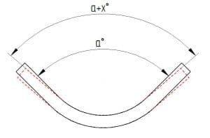
Bending Springback
When bending a workpiece, it will naturally spring back a little after the load is lifted. Therefore, it has to be compensated for when bending. The workpiece is bent beyond the required angle, so it takes the wanted shape after springback.
Another thing to keep in mind here is the bending radius. The larger the inside radius, the bigger the springback effect. A sharp punch gives a small radius and relieves the springback.
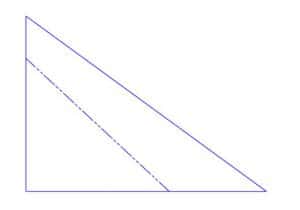
Why does springback occur? When bending parts, the bend is divided into two layers with a line separating them – the neutral line. On each side, a different physical process is taking place. On the “inside”, the material is compressed, on the “outside”, it is pulled. Each type of metal has different values for the loads they can take when compressed or pulled. And the compressive strength of a material is far superior than the tensile strength.
As a result, it is more difficult to reach permanent deformation on the inner side. This means that the compressed layer will not get deformed permanently and tries to regain its former shape after lifting the load.
Bend Allowance and K Factor
If you design your bent sheet metal parts in CAD software that has a special sheet metal environment, use it. It exists for a reason. When making bends, it takes material specifications into account. All this information is necessary when making a flat pattern for laser cutting.
Unless you use our manufacturing service where CAD models are accepted for production, you need to keep producing those flat pattern drawings.
If you make your flat pattern drawings yourself, here’s something you need to know. Bending elongates the material. This means that the neutral line or axis, as we talked in the springback section, is not really in the middle of the material. But the flat pattern must be formed according to the neutral line. And finding its position requires k factor.
K factor is an empirical constant, meaning that its value was determined by testing. It varies according to material, its thickness, bend radius and bending method. Basically, the k factor offsets the neutral line to provide a flat pattern that reflects reality. By using it, you get the bend allowance which is, in essence, the length of the curved neutral axis.
K factor formula:
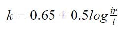
k – k factor, constant; ir – inside radius (mm); t – sheet thickness (mm)
Bend allowance formulas:
For bends between 0 and 90 degrees, the formula is as follows:
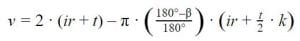
ß – bending angle (°)
For bends between 90 and 165 degrees the formula is:

For bends over 165°, there is no need to calculate bend allowances, as the neutral axis stays pretty much in the middle of the detail.
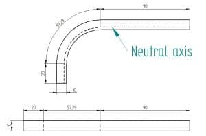
Calculating Bend Allowance
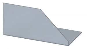
Let’s say you have a similar part to the one on the image above – it has a straight leg of 20 mm and another of 70 mm. The bending angle is 90°, the sheet thickness is 5 mm and the inside radius is 6 mm. We want to know the final length of the detail. First, we must start with the k factor:
![]()
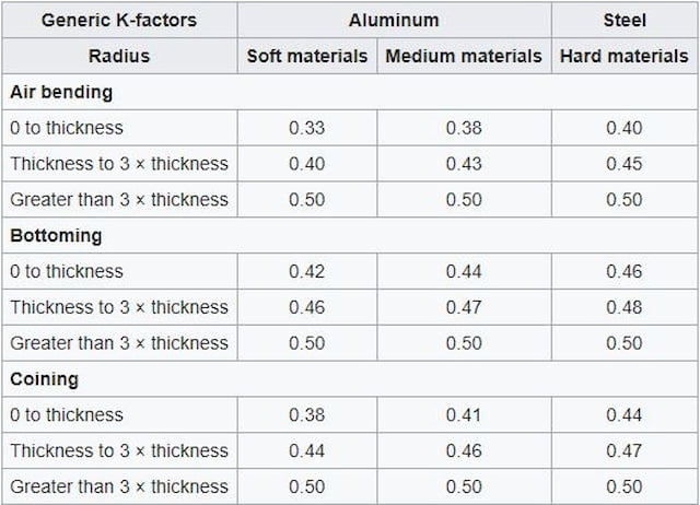
Another way to determine the k factor is by following the “rule of thumb”. Just select a k factor according to your material from the table below. This gives results accurate enough for most cases.
Now we can move on to the bend allowance:

For the final length we just add the two leg lengths to the bend allowance:
![]()
Sheet Metal Design Tips for Bending
So, I talked to our experienced sales engineer who knows his bit about sheet metal bending. He lit up and decided to make the fullest of the opportunity to share his insights on sheet metal bending. Thus, he brought out a list of common mistakes and the solutions to avoid them.
Minimum Flange Length
There exists a minimum flange length, as stated already before. See the bending force chart for guidance. According to thickness, the die width is selected. If you design a flange that is too short, it will “fall” awkwardly into the crevice and you won’t get the result you’re looking for.
Chamfered Sides
If you want to make a flange that has one or two ends chamfered, the previous rule of a minimum flange length still applies. The chamfers have to leave enough room to accomplish proper bends, otherwise it will just look deformed and nobody’s really satisfied.
Hole Distance from Bend
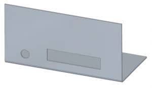
If the holes are too close to the bend, they may get deformed. Round holes are not as problematic as other types but your bolts may still not fit through. Again, see the bending force chart for minimum flange measurements and put the holes farther than the minimum.
Symmetry
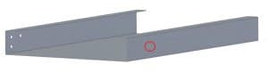
There lies a great danger in making parts that are almost symmetric. If possible, make it symmetric. If it is nearly symmetric, the bending press operator may get confused. The result? Your part will be bent in the wrong direction.
The symmetry cannot be guaranteed in every instance, but then make sure that it is easily understood how the manufacturing should be done.
Rivet Nuts
If you use rivet nuts near the bending line, it’s known that inserting them before bending is good for securing its applicability. After bending, the holes may be deformed. Still, make sure that the nuts won’t be in the way of tools when bending.
Small Flanges on Big Parts
It is better to omit small flanges with big and heavy parts. It makes manufacturing very difficult and manual labour may be needed. But it costs more than simple machining. As a result, it is wiser to opt for an alternative solution, if possible.
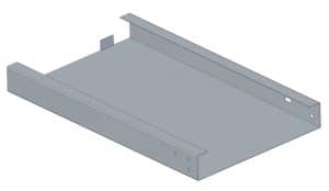
Bends Next to Each Other
If you want to include successive bends, check if it’s feasible. A problem arises when you cannot fit the already-bent part onto the die. If your bends face the same direction – a U-bend -, then a common rule is to make the design the intermediate part longer than the flanges.
Keep the Bends on the Same Line
It is best to keep the bends on the same line in case you have several flanges in succession. With this in mind, you can keep the number of operations at a minimum. Otherwise, the operator needs to readjust the parts for every single bend, which means more time and more money.
The Bending Line is Parallel to a Side
As the headline says. There has to be a parallel side to your bending line for positioning purposes. If not, aligning the part is a real headache and you may end up with an unsatisfactory result.
Bend Relief
To get the best outcome, it is advisable to make not only a small laser cut incision but an actual cutout on the sides of the flange-to-be – a bend relief. The width of such a cut should be above the material thickness. This ensures that there are no tears or deformations to the final bend. Another good practice here is to include small radii to the bend reliefs, as they also relieve material stress.
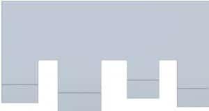
Bending a Box
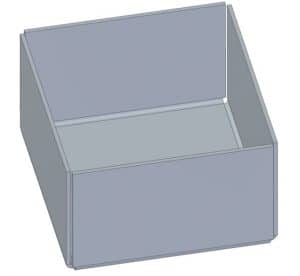
When bending a box, small gaps should be left between the flanges. Otherwise, the last bend can crash into the existing ones, breaking the whole structure.
Check the Flat Pattern
One thing to keep in mind is switching your CAD view to flat pattern from time to time. There are many upsides to that. Firstly, if you get carried away with your flanges, you may end up with something that cannot exist in flat pattern. What cannot exist in flat pattern, cannot exist in any other way.
Measure the layout. Maybe you can adjust the design for optimal fit. Try to avoid going for a bigger sheet if the smaller size is within reach. Maybe you could fit 2 pieces onto the same sheet if you just shed a few millimetres off? It will reflect on the final price quotation.
Rule of Thumb for Minimum Bend Radius
Keep it simple. What could be simpler than choosing the inner radius (ir) just the same as the material thickness? This avoids later troubles, overthinking and silly mistakes. Dropping below that value can bring problems your way. A larger radius will just make some other calculations a little more difficult.
Bending Direction
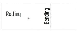
You should not design your bends in the same direction as the material rolling was done. This is especially important with aluminium and Hardox. Of course, we all know the aluminium casing with 4 sides that needs bending operations contrary to what we are suggesting. Still, it is better to avoid it if possible. The result can be uneven surfaces or even cracking.
Although manufacturing engineers take care to notice these things, it is good to notice them yourself. It helps to account for material usage.
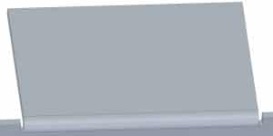
Hemming

If you want to strengthen the edges of your metal sheet, hemming is a great option. Still, some advice applies. It is better to leave a small radius inside the hem. Completely crushing the radius needs great power and tonnage. Also, it puts the material in danger of cracking. Leaving a radius, on the other hand, relieves this danger.
Consider the Material
The regular thin 1…3 mm structural steel sheets can pretty much take anything. After that, you need to do your research. Some materials are much more capricious about the way they are handled. Getting a good result depends on your knowledge and on the help your production engineer is able to provide.
Metal Bending Online
Fractory offers the aforementioned possibilities on a web-based platform. Getting an online bending quote is very easy, you just have to upload your 3D files (STEP, SLDPRT, IPT) onto our platform and the price and lead time will be displayed on your screen almost instantaneously.
Our capabilities:
Maximum force: 1000 tonnes
Maximum bending line length: 7200 mm
Maximum material thickness: 60 mm
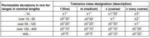
If there are no extra requirements from the customer, then by default ISO standard tolerances (class m) are applied to our products. Bending tolerances are shown in the table above.
