

Surface roughness is a term frequently used in mechanical drawings and engineering discussions to describe the texture of a surface. It is a crucial parameter that defines surface characteristics and can be quantified in various ways, each of which is significant for specific applications. The goal of this article is to explain this essential surface feature in a clear and accessible manner, fostering a solid foundational understanding of its concept.
- Surface roughness defines the microscopic texture of a surface. It measures tiny peaks and valleys that affect friction, wear, lubrication and cleaning.
- Specifying surface finish optimises cost and quality, and ensures that the part functions as designed.
- Surface roughness is a part of surface finish. Surface finish includes roughness, form, lay and waviness—each critical for functionality.
- Ra and Rz are key surface roughness parameters. Ra is the average deviation, Rz is the average peak-to-valley height. Rz is usually higher and more representative of extremes.
- Surface roughness symbols communicate roughness values, machining needs and finish types on drawings.
- Several measurement methods are available. Comparators are quick but rough; stylus profilometers are accurate but slow; optical and atomic force microscopy offer non-destructive testing options.
What Is Surface Roughness in Manufacturing?
Surface roughness is a parameter that characterises a surface texture in relation to its ideal form. It uses standardised expressions and symbols to convey all necessary information concisely.
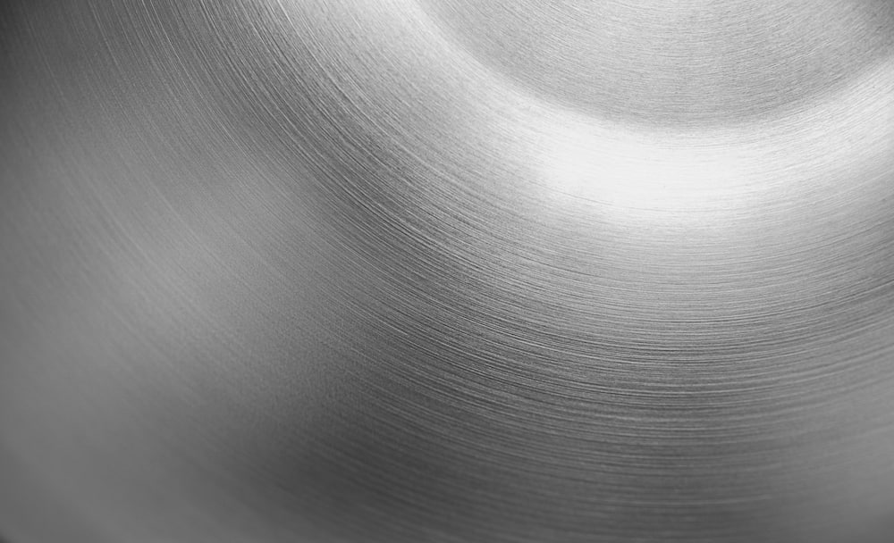
Even a seemingly smooth surface, when examined under sufficient magnification, reveals a composition of jagged peaks and valleys. The greater the peak and valley height, the rougher the surface.
These microscopic peaks and valleys serve crucial functions, such as enhancing friction and retaining lubrication oil between two sliding surfaces. However, depending on the application, their amplitude must remain within specific ranges.
If the maximum height and depth of peaks and valleys are excessive, it can result in problems such as increased wear and tear, corrosion and fatigue failure. High surface roughness can also impair the performance of seals and disrupt fluid flow. It also makes cleaning more difficult.
On the other hand, very smooth surfaces can reduce lubrication capability and grip, leading to high temperatures and slippage of parts during operation. Additionally, they are more expensive and time-consuming to manufacture, and they have a higher potential for damage.
Furthermore, the smoothness-to-benefit ratio is no longer proportional; that is, extremely smooth surfaces do not provide a corresponding performance bump beyond a certain threshold. Moreover, smooth surfaces have fewer practical applications in the real world.
Why Is Surface Roughness Important?
Quantifying surface roughness is crucial, as achieving perfect surfaces in manufacturing is nearly impossible. This is particularly relevant for commercial products that require short cycle times and strict cost control. Irregularities can occur in all manufactured surfaces due to various factors.
Surface roughness measurement identifies and quantifies irregularities for quality control purposes. By establishing acceptable deviation limits, we can optimise the cost and time associated with manufacturing products to meet specific functional and aesthetic specifications.
Parts produced through CNC manufacturing, mouldings, extrusions, 3D printing, and other methods have their surface roughness predetermined to ensure that each component not only functions as intended but also meets budget and production timelines.
Surfaces that do not meet the desired surface finish can always undergo additional finishing processes to achieve the required quality.
Difference Between Surface Roughness and Surface Finish
Surface finish is a comprehensive indicator that reflects the overall condition of a surface, incorporating additional parameters such as waviness, lay and form, in addition to surface roughness. These parameters can render a part unusable, even if it meets the surface roughness criteria. Therefore, it is essential to understand and define these parameters to prevent costly corrections downstream.
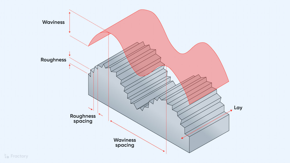
Form, Lay and Waviness
Form refers to the ideal shape of a component. In most cases, it is impossible, and often unnecessary, for a component to achieve its ideal form. The form provides a blueprint outlining the shape and dimensions required for the component to function as intended. The ideal form is always accompanied by tolerances that define the permissible range of deviation, ensuring that the component can still fit and function correctly.
Lay refers to the dominant pattern on a surface that develops as a result of manufacturing processes. The intensity and orientation of the lay pattern depend on the specific manufacturing method used, which can vary significantly between processes such as metal casting, hot and cold rolling, and others. Lay patterns can take on various forms, including parallel, perpendicular, grid, radial, concentric, multi-directional and non-directional. Each pattern is represented by a distinct symbol for quick identification.
Waviness refers to the formation of a wave-like pattern on a surface. The wavelength of waviness is larger than the sampling length, necessitating its separation and consideration during surface roughness measurements. Waviness can occur due to imperfections in manufacturing processes, such as oscillating lead screws, tool blemishes, vibrations, chatter or material strains.
Surface Roughness Parameters and Symbols
Surface Roughness Parameters
We can quantify surface roughness using various parameters. These parameters are obtained through measurement methods that will be discussed in the following sections. Generally, surface parameters in metrology fall into two categories: profile parameters and areal parameters.
Profile parameters are calculated along a line using two-dimensional measurement processes, such as stylus profilometry. They are denoted by the letter ‘R’ followed by an additional character. In contrast, areal parameters assess the entire surface using optical non-contact measurement techniques. These methods generate a three-dimensional map of the surface. Areal parameters are represented by the letter ‘S’ followed by another character.
Profile Parameters
Two of the most commonly used profile parameters are average roughness (Ra) and mean roughness depth (Rz).
Average roughness, or Ra, is primarily used in the United States and is calculated by integrating the absolute values of the peaks and valleys over the sampling length, then dividing that sum by the sampling length.
The formula for the average roughness (Ra) is given by Ra = (1/L) ∫ |y(x)| dx from 0 to L, where:
-
L represents the sampling length.
-
x represents the distance from the measurement point to the origin.
-
y(x) represents the deviation of the surface from the mean line.
The Ra value can be specified in micro-inches or micrometers (microns). Just as 1 meter is equal to 39.37 inches, 1 micrometer (micron) is equal to 39.37 micro-inches.
Mean roughness depth, or Rz, is the internationally preferred measurement. To calculate Rz, the roughness profile is first divided into five equal sections. For each section, the difference between the highest peak and the lowest valley is calculated (denoted as Rt). Rz is then determined as the average of the five Rt values.
For Ra and Rz, a lower value indicates a smoother surface. However, it is important to note that Ra tends to underestimate surface variations, and its value is almost always lower than that of Rz.
Moreover, since Rz relies solely on the furthest points in its calculation, rather than considering the entire surface as Ra does, its value is consistently greater than that of Ra. In most instances, Rz = 7.2 x Ra.
Other important profile parameters when working with surface roughness include:
-
Rp – The maximum height of a peak from the mean line.
-
Rv – The maximum valley height measured from the mean line.
-
Rmax – The maximum distance between the highest peak and the lowest valley within the sampling length.
-
RMS – The root mean square (RMS) is the average of the peak and valley height variations from the mean line.
Areal Parameters
Areal parameters provide a more comprehensive overview than profile parameters. They are independent of direction and include a lot more measuring points compared to profile parameters. Some commonly used areal parameters include the following:
-
Sa – Arithmetic mean height of the surface
-
Sq – Root mean square height of the surface
-
Sp – Maximum peak height
-
Sv – Maximum valley height
-
Sz – Maximum peak-to-valley height over the evaluation length
- Personal account manager
- Quality assurance
- Payment terms for companies
- On-time delivery by Fractory
Surface Roughness Symbols
Surface roughness specifications are indicated on technical drawings using a check-mark-shaped symbol. This symbol is accompanied by numbers and additional markings that define the surface texture parameters, such as roughness values, production methods, machining directions, and lay orientation. The position of each value relative to the symbol determines what it represents:
-
Left side: Minimum material removal requirement.
-
Between the two lines: Average roughness (Ra) value.
-
Right side: Additional parameters (e.g. Rz) or secondary surface requirements.
Modifications to the symbol convey further details:
-
A bar across the shorter leg indicates that material removal by machining is required.
-
A circle signifies that no further machining is permitted — the required finish must be achieved directly from processes like casting, forging or moulding.
-
A horizontal extension allows additional notes such as production method, coating or treatment details.
These conventions are defined in ASTM Y14.36M in the United States. In the UK and EU, the equivalent is ISO 1302:2002 (superseded by ISO 21920-1:2021 under the Geometrical Product Specification framework).
While the basic symbol form is similar, there are minor differences:
-
Value placement rules are slightly different.
-
ISO places greater emphasis on Ra/Rz notation consistency.
-
Some lay and machining indicators vary in format or orientation.
Because of these variations, it’s important to verify which standard applies before interpreting or creating technical drawings.
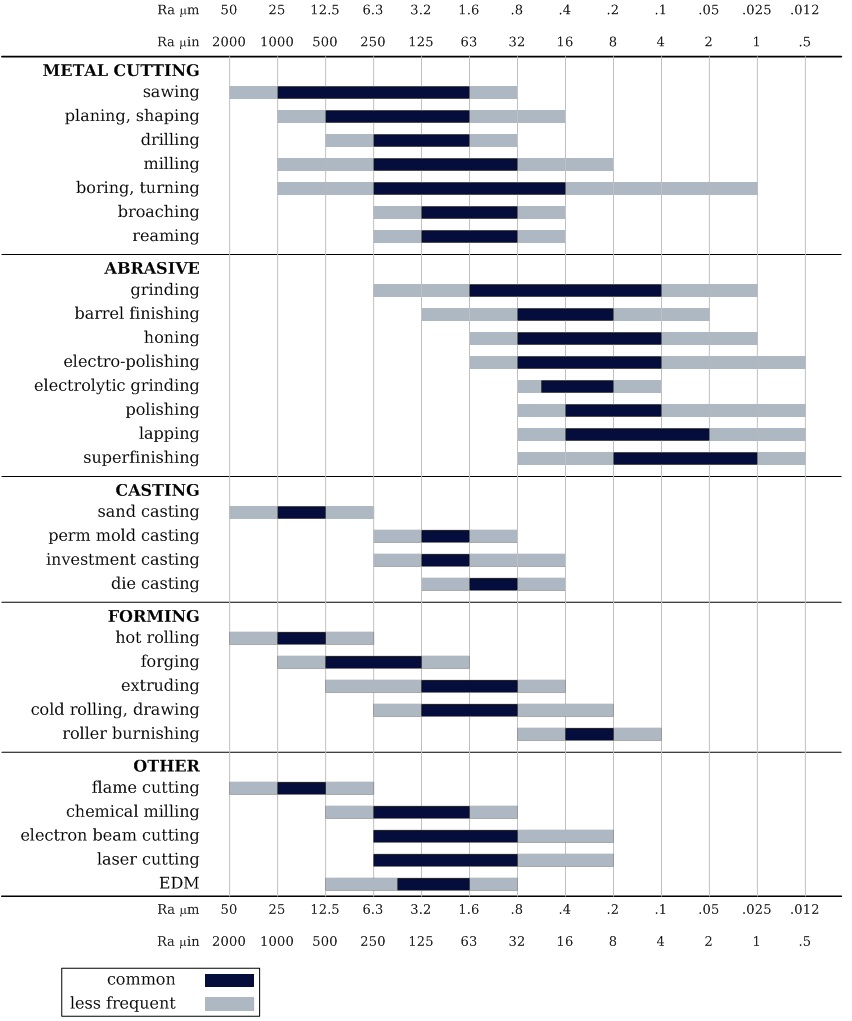
Surface Roughness Comparison Chart by Manufacturing Processes
How to Measure Surface Roughness
There are several methods for measuring surface roughness, each with its unique advantages and limitations. In this section, we will cover the following measurement techniques:
-
Surface roughness comparator
-
Stylus profilometer
-
Non-contact methods
-
Atomic force microscopy
Surface Roughness Comparator
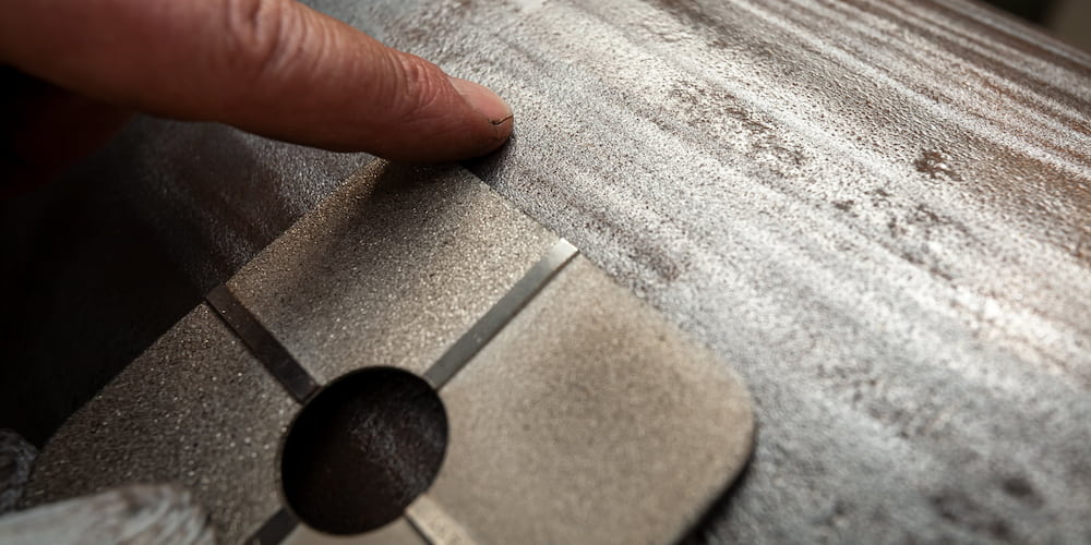
One effective method for quickly assessing the surface profile of a metal is to use a surface roughness comparator. Surface comparators are flat steel plates that feature four to five reference surface profiles, which allow users to evaluate an unknown surface. Users can compare the two surfaces both visually and through tactile examination to determine whether the surface has achieved the desired texture or roughness. To enhance visual inspection, the kit may also include an illuminated magnifier.
Their compact and portable design allows users to quickly assess rough surfaces in the field. Surface roughness comparators are specifically engineered for surfaces resulting from processes such as sandblasting and shot blasting (including bead and grit blasting). Once the inspection is completed satisfactorily, the surfaces can be sent for further processing or painting.
However, surface roughness comparators provide a qualitative assessment. This comparison is subjective and has limited accuracy, as it heavily depends on the operator’s skill and experience. Additionally, these comparators fail to capture other important surface characteristics, such as waviness. The waviness profile significantly influences how a surface interacts with its environment.
Moreover, there is a lack of standardisation, which makes it difficult to compare sets from different manufacturers. Additionally, comparators wear down with use and therefore require periodic recalibration or replacement to prevent errors.
Stylus Profilometer

When an exact surface roughness value is required, it is typically measured using a surface roughness profilometer. A profilometer is a precise instrument designed to measure the microscopic surface geometry of sample surfaces. The stylus profilometer is the most basic type of profilometer and is also more cost-effective compared to other types.
The stylus profilometer features a stylus tip that is drawn across the surface to be measured. According to ISO standards, the profilometer employs a conical stylus with an angle of either 60° or 90° and a spherical tip measuring 2 μm. Typically, the profilometer utilises a sapphire or diamond stylus.
As the stylus moves horizontally across the surface, it captures the vertical distance of the surface features and replicates this information on a recording device. A profilometer can also measure additional surface parameters, such as surface waviness.
Stylus profilometry is renowned for its precision. Depending on the measurement range, it can measure Ra values as low as 0.005 μm and Rz values down to 0.02 μm.
However, it does have certain limitations. For instance, the stylus of a profilometer can scratch or deform delicate surfaces. Additionally, surface measurements typically take significantly longer than non-contact methods, which is a disadvantage in manufacturing processes where high speed is essential.
The stylus profilometer may encounter difficulties when measuring surfaces with high aspect ratio features or those composed of viscous materials.
Non-Contact Methods
Some of the issues associated with stylus profilometers can be mitigated by employing non-contact methods, such as optical profilometers. In this equipment, instruments like white light and confocal replace the stylus. These methods are non-destructive and use techniques such as interferometry to generate a three-dimensional map of the surface.
However, these profilometers are more expensive than stylus profilometers. Additionally, the requirement for sophisticated software and algorithms can occasionally lead to inaccurate measurements, particularly for surfaces with complex topographies or those that are highly reflective or glossy.
Atomic Force Microscopy

Atomic force microscopy (AFM) is a special non-contact measurement method to measure surface roughness at the nanometer level. The AFM method uses a sharp probe, also known as a cantilever, that hangs just above the surface without touching it. As the probe scans the surface, it deflects due to the attractive and repulsive forces between it and the surface.
To measure the deflection of the probe, a laser beam is aimed at the back of the cantilever. The beam reflects off the cantilever onto a position-sensitive light sensor. When the probe moves, the laser beam’s reflection moves proportionally. The change in reflection is read and analysed to create a high-definition 3D topographic image of the surface.
AFM is used in highly specialised, niche applications in biotechnology, nanotechnology, materials science, and semiconductor manufacturing.
Wrapping It Up
Surface roughness is a critical parameter that influences everything from performance to aesthetic appeal. These irregularities, as microscopic as they are, play a vital role in how materials interact, wear and function in service.
Understanding the difference between surface roughness and surface finish and parameters like Ra and Rz enables engineers to define surface roughness requirements that optimise for manufacturability, cost and performance
Measurement methods, ranging from simple comparators to atomic force microscopy, offer varying levels of precision depending on the application. Prudent integration of surface roughness into workflows enables manufacturers to reduce failure rates, control costs and create products that can be depended on.
Surface engineering evolves every day, but mastering the basics of surface roughness and the important role it plays in product design will remain essential for anyone involved in metrology, machining and quality assurance. A well-informed approach to surface roughness lays the foundation for well-designed, long-lasting products.
