

ASME Y14.5-2009 divides tolerances in GD&T into 14 different types. Each tolerance controls the characteristics of features to guarantee near-perfect fabrication and assembly of machine components. These 14 tolerances are sorted into five groups based on the characteristics they control. These groups are form, profile, orientation, location and runout.
Under orientation control, we have parallelism, perpendicularity and angularity tolerances. These tolerances control the orientation of a feature (such as a line, axis or surface) in respect to another reference feature (datum element).
In this article, we will explain the concept of parallelism GD&T tolerance. We will also go over its tolerance zone, feature control frame and measurement methods.
What Is Parallelism in GD&T?
Parallelism is a 3D GD&T orientation tolerance which maintains that two part features are parallel to each other. You can use it to control centerlines, center planes, cylindrical and planar surfaces parallel to the datum elements.
There are two types of parallelism in GD&T. It may either refer to surface parallelism or axis parallelism depending on whether you use it to control a surface or an axis. The use of surface parallelism is more common than axis parallelism.
With both types of GD&T parallelism, the goal is to maintain parallelism (0° alignment) with the datum element (axis or plane) according to the limits specified in the feature control frame.
Parallelism Tolerance Zone
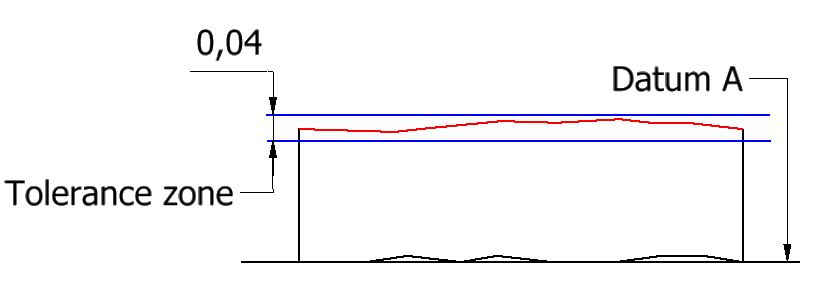
In the case of surface parallelism, the parallelism tolerance zone is made of two theoretically exact parallel planes. The distance between the two planes is the tolerance limit for the callout. All the points on the planar surface or center plane must lie within the two parallel planes for a part to be approved.
It is evident from the shape of the zone that the parallelism tolerance doesn’t create an angular tolerance zone to control the 0° alignment between the controlled surface and the datum plane.
Instead, it fixes the tolerance zone at a basic (or exact) 0° angle and the permissible variation is controlled by widening or tightening the two surfaces of the zone. The greater the distance between the zone’s two planes, the more error it can accommodate.
Axis parallelism creates a cylindrical tolerance zone. It is used to maintain the axis of a feature of size such as cylindrical pins or holes parallel to a datum. All the points of the feature’s center axis must lie in this cylindrical zone for a part to be in spec. In this type of zone, the permissible angular deviation can be controlled by reducing or increasing the diameter of the cylindrical zone.
It is worth mentioning here that the parallelism callout cannot control the location of the tolerance zone. It is only concerned with orientation. The tolerance zone exists at the location of the surface.
- Personal account manager
- Quality assurance
- Payment terms for companies
- On-time delivery by Fractory
Parallelism vs Other Callouts
Due to many similarities between parallelism and some other tolerances, it is often confused with flatness and other orientation controls. It is advisable to understand the difference between them for their correct application in GD&T.
Parallelism and flatness
Parallelism and flatness resemble each other on many levels. They both have similar tolerance zones. They essentially control the flatness of the surface they are applied to. Their measuring methods are identical.
There are some key differences though, that help us distinguish between the two. For instance, parallelism, as with all other orientation controls, cannot function without a datum. The surface’s tilt is compared with a datum plane to create the tolerance zone.
On the other hand, when flatness tolerance is used, the surface is measured against itself. The tilt does not matter as long as the flatness is within limits. With the parallelism callout, the zone may translate or shift but it cannot tilt in respect to the datum.
Parallelism and angularity
Parallelism and angularity are both orientation controls. They are similar in almost every way except that angularity can maintain part features at any angle between 0 and 90°, whereas parallelism can only maintain a 0° angle.
Perpendicularity, on the other hand, is used for perpendicular orientations. Many books refer to parallelism and perpendicularity as refined forms of angularity. Angularity can replace both parallelism and perpendicularity in all cases but the opposite is not true.
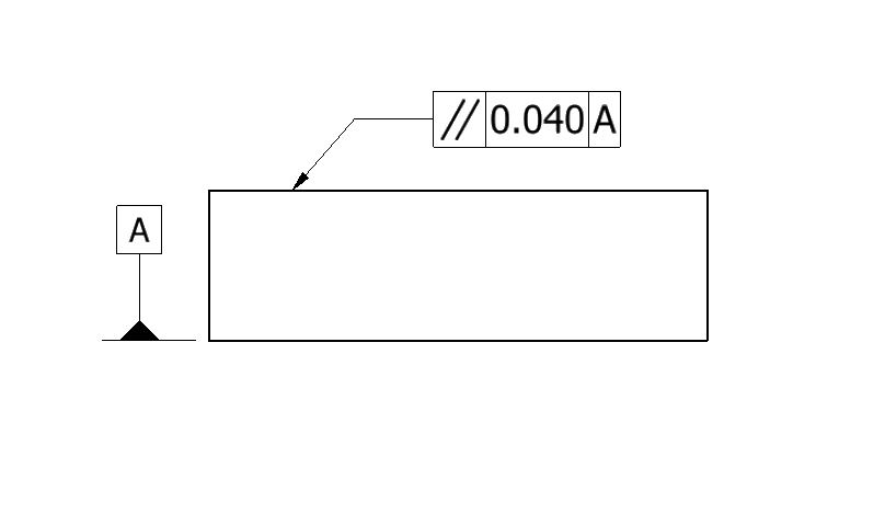
Parallelism Feature Control Frame
The parallelism control is applied to part features through feature control frame (FCF). A leader arrow points the FCF to a feature or its extension line. A generic FCF is divided into three main blocks for ease of understanding. These blocks are:
-
Geometric tolerance block
-
Tolerance block
-
Datum block
Geometric tolerance block
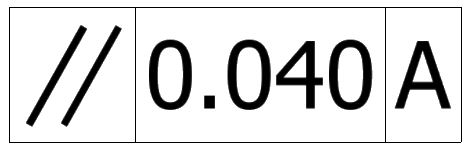
This block contains information about what geometrical tolerance is being applied to the feature. In our case, it will contain the parallelism symbol. The parallelism symbol consists of two oblique parallel lines (//).
Tolerance block
This block shows how a GD&T callout applies to a feature. The first symbol in this block is for the shape of the tolerance zone.
In the case of axis parallelism, the zone’s shape is cylindrical which is represented by a diameter symbol in this block. For surface parallelism, the zone is made of two parallel planes. This is the default zone in GD&T and does not require a symbol.
The next component is the tolerance value. For axis parallelism, the value is the diameter of the cylindrical zone. For surface parallelism, this value is the distance between the zone planes.
The next symbol is for the surface modifier. When parallelism tolerance is in reference to a surface plane, material modifiers cannot be used. But in the case of axis parallelism, both LMC (least material condition) and MMC (maximum material condition) are allowed. The bonus tolerance (difference between LMC/MMC and the actual condition) comes into the picture when we apply these modifiers.
Axis parallelism is not commonly used but check out our article on perpendicularity for a more detailed overview of how an axis is controlled in GD&T.
Datum block
Many GD&T callouts are called in reference to a datum feature. The third block in the FCF houses the datum symbol. As with other orientation controls, parallelism cannot be called without a datum element.
How to Measure Parallelism
Parallelism and flatness have similar measurement methods, except that in parallelism the part must be held against a flat surface that acts as the datum element.
A CMM is the most accurate tool to measure parallelism. However, in the absence of one, an inspector may use a surface plate and height gauge to measure parallelism with reasonable accuracy.

To measure parallelism using a surface plate and a height gauge, the inspector follows the following steps:
-
Place the datum surface from the FCF against the surface plate. The surface plate now acts as a datum simulator creating a theoretical reference plane. This plane is known as a ‘simulated datum’ in ASME Y14.5 M.
-
Set the dial indicator at a fixed height with its probe touching the surface under control.
-
Reset the dial indicator to zero.
-
Sweep it across the entire surface and record the highest and lowest values obtained. Subtract these values from each other to obtain the full indicator movement (FIM) for the surface.
-
Compare the FIM value to the tolerance limit. For a part to be in spec, this value must be smaller than the tolerance limit.
Important Points to Remember
-
Parallelism can never be called without a datum feature.
-
Due to the envelope principle (GD&T rule #1), the parallelism tolerance cannot be greater than the size tolerance.
-
Temperature becomes an important factor when measuring parallelism with extremely small tolerance limits as some materials expand/contract more than others with temperature.
