

We know that manufactured products can never match their theoretical drawings perfectly. The actual size varies from the intended design. The goal of GD&T is to hold this variation within set limits.
True position is a GD&T callout for specifying the position of a feature. It is more correctly referred to as “position”. We use this concept in GD&T to control the variation of a specific feature from its desired position. This is important for mating parts to ensure a seamless assembly.
For example, the screw holes on a cylinder head cover must match the screw holes on the engine casing in size as well as position. In the event that they don’t, the two parts will not mate, and the lubrication oil for the valve assembly will leak out, defeating the purpose of the cover. The cylinder cover is useless, and a different piece must be used.
To prevent this from happening, we use position tolerances as guidance for CNC turning and milling services.
The position symbol is an extremely useful one but its application may be a bit complicated. In this article, we shall learn the basics of this feature callout and how to apply this tool to different material conditions.
Definition of True Position
The true position tolerance in GD&T informs us of the maximum allowable deviation of a feature (e.g. hole, slot) from its true position. By true position, we mean the ideal position of the feature according to design.
The idea is that, for a feature, there is a true position that we desire. We define datum planes and axes as references to define the exact placement.
Then, we mark the true positions of the features of size using basic dimensions. We take into account any material condition modifiers if needed.
Position is a 2D/3D tolerance in GD&T that defines tolerance zones depending on the feature. For cylindrical features, it creates a cylindrical tolerance zone around the true position of the feature within which the axis of the feature must lie for all manufactured products.
For other features, parallel planes are defined within which the centre plane of the feature must lie for approval.
Difference Between Position and True Position
In the ASME Y14.5 standard, the true position callout is referred to as just “position”. “Position” is the correct way to term it as we know that true position actually refers to the theoretical point on the surface with basic dimensions which is impossible to replicate in actual products.
However, in CNC machining vernacular, the term true position is more popular when referring to the feature’s position on the actual product.
Therefore, when we use the term ‘true position’ in the article, more often than not, we actually mean the position of the manufactured feature in relation to the actual true position and not the true position (exact dimension or nominal value) of the feature.
- Personal account manager
- Quality assurance
- Payment terms for companies
- On-time delivery by Fractory
True Position vs Linear Tolerancing
Using positional tolerance actually enables designers to use looser tolerances. There are many advantages to using looser tolerances and that’s why it becomes imperative for us to use them wherever possible. Let us see how using GD&T makes it possible by evaluating two scenarios with similar tolerance specifications.
True position
Consider a hole defined with a positional tolerance of 1 mm. This defines a circular tolerance zone of the radius 0.5 mm around the true position. The axis of the manufactured feature must lie within this ⌀1mm circle, meaning the maximum distance from the intended axis spot is the same in every direction.
Now, consider a point within this tolerance zone at a distance of 0.25 mm from the X-axis and 0.25 mm from the Y-axis (considering the true position as origin).
At this point, the position of the feature is calculated as ~0.7 mm, as position = 2 x √(x2 + y2). This number lies within 1 mm, and so, the final product is within the acceptable range.
If we want this position to be the upper limit, we will have to define the positional tolerance as ⌀0.7 mm.
Plus/minus tolerancing
Now, let’s compare this with plus/minus tolerancing.
Plus/minus tolerancing refers to the traditional method of assigning tolerances to feature dimensions. Due to the upper and lower limits assigned in each direction, the resultant tolerance zone is a square.
To accept the manufactured product above, we would have to set up a tolerance limit of ±0.35 mm (Total tolerance width = 0.7 mm). This would define a square of side 0.7 mm.
At the same time, the corners of the square are further away than the sides. This means that the tolerance given using X and Y axes is not uniform in every direction.
Comparison
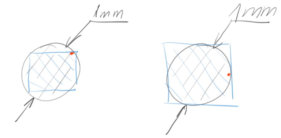
For the same point to lie in both tolerance zones, the circular tolerance zone will circumscribe the square tolerance zone. If we compare the area of two zones, the area of the circular zone exceeds the square zone.
We can calculate the extra zone by dividing the area of the circumscribed circle by the area of the square. In all cases, we get a 57% increase in the zone when we prefer the positional tolerance over the plus/minus tolerance.
Thus, for the same deviation, we can use looser overall tolerance and still accept the part. This reduces the part manufacturing cost.
This can be a bit difficult to comprehend. We must ask ourselves the question: Why is a part acceptable when the manufactured feature’s axis is at a distance of 0.7 mm at the corners of a square but not acceptable in all 360 degrees?
Using true position helps us exploit the extra 57% area while essentially maintaining the same limit.
Characteristics of the Tolerance Zone
The tolerance zone using true position may appear in two ways depending on the callout used – cylindrical and square.
Cylindrical tolerance zone
The true position symbol in GD&T is represented using a crosshair symbol (⌖). When we use the callout with a diameter symbol (⌀), we get a cylindrical tolerancing zone and this is how it is intended to use most of the time.
Usually, we set a datum to fix the true position as per our design. Sometimes, we may use multiple datums to accurately locate the feature. We denote this reference point using basic dimensions.
This true position acts as our reference to measure the deviation of the actual manufactured parts. The true position is usually set at the centre of the feature being toleranced. For example, for a hole, the true position is set at the hole’s axis. Around it, we define the 2D or 3D diameter tolerance zone based on the feature characteristics.
So, we have a reference axis for the hole at the true position and the tolerance zone sets the limit up to which the actual part feature’s axis may stray.
The 3D tolerance zone is basically a virtual cylinder fixed around the hole axis at the tolerance value and goes through the entire thickness of the part.
Square tolerance zone
Without using the diameter sign, the true position tolerance refers to exactly the same square zone like the traditional linear tolerancing does.
This creates a tighter tolerance zone as explained before and hence is rarely used. We may lose more than 36% of the tolerance zone by using the callout in this manner.
How to Use True Position
True position is one of the most extensively used callouts in GD&T. It is often used in lieu of concentricity and symmetry which also belong to GD&T location controls group. We can control and measure the location of different features more easily with true position as it provides a standardised method to express the location dispelling any confusion.
To understand how to apply true position to a feature, we need knowledge of the feature control frame.
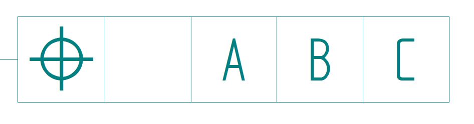
Briefly, the feature control frame consists of three main blocks.
- Geometric characteristic symbol
- Tolerance value and any material condition modifier
- Datum planes or axes
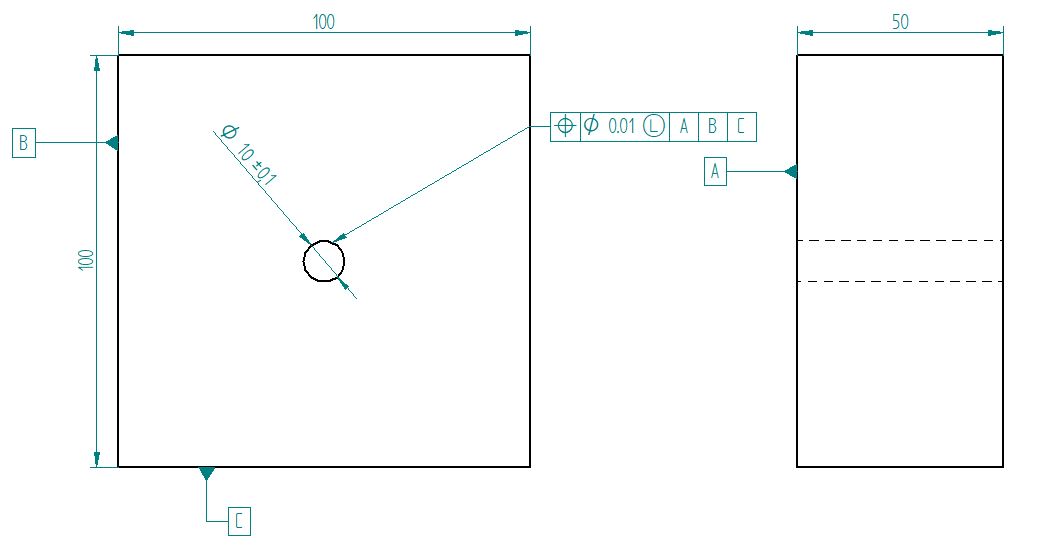
Let’s suppose we need to display, on our drawing, the true position and positional tolerance of a hole lying at the centre of a workpiece that measures 100 x 100 x 50 mm(l x b x h). The size of the hole is ⌀1 mm with a tolerance of ±0.005 mm.
Selecting the type of geometric characteristic
Since we are denoting true position in the feature control frame, we will denote it using its assigned symbol of the crosshair (⌖) in the geometric characteristic symbol block.
Selecting datums
We start with selecting our reference datum plane. We can use a minimum of one datum. Datums could be points, lines, or planes.
In this sample example, we will select three datum planes. We name them in decreasing order of importance.
For our first datum, we will select the bottom plane of the workpiece. We will name it A. This datum specifies that the hole centre axis must be perpendicular to this plane. This is a form of perpendicularity control.
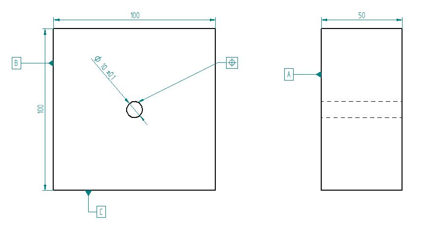
For our 2nd and 3rd datums, we will select the planes of the left and front face. We will mark these datums as Datum B and C respectively on our engineering drawing.
Then, we will mention the distance of our feature (hole) from datum planes B and C on the drawing. In this case, it is 50 mm for both as the hole position is at the centre. These distances are shown as basic dimensions and are enclosed in a box to express the same.
In the feature control frame, we will write down A, B, and C, in the 3rd, 4th, and 5th blocks respectively.
Expressing the tolerance zone and values
In this example, we will use the cylindrical tolerancing zone. We will denote this in the feature control frame using the diameter symbol (⌀).
Following this, we shall denote the total tolerance width as 0.01 mm (±0.005 mm).
Material condition modifiers
If there are any material condition modifiers present, we add them after the tolerance value. A circled ‘M’ for maximum material condition (MMC), or a circled ‘L’ for least material condition (LMC). MMC is used more commonly than LMC.
True position tolerance is used very often with a material condition modifier. Parts are toleranced at these limits to ensure that they do not interfere when mating or if they do, it happens in a limited manner even when they are at their tolerance limits.
MMC for a shaft is the largest allowable size (diameter), and for a hole the smallest allowable size. We can ensure that there is always some clearance between the two by ensuring that the MMC of the shaft is less than the MMC of the hole in our designs.
When we add this modifier to our true position control frame, it specifies that we are applying the tolerances at the maximum material condition to ensure that a hole is not too small or a shaft too big at any point throughout the depth of the feature. Thus, with this size of feature control, we can control the orientation besides the size and location.
How to Calculate and Measure True Position
The true position feature provides many uses. But when it comes to inspection, it is a bit complicated. Let’s start with how to calculate the position of a manufactured part with respect to the true position of the feature.
The true position is calculated using the following formula:
True Position = 2 x Square root[(Measured X – True X)2 + (Measured Y – True Y)2], where
Measured value – Reading obtained by measuring instruments.
True value – True position stated using basic dimensions.
These calculations can be done with a simple calculator or manually as it is basically twice the value of the hypotenuse obtained through the Pythagorean theorem.
If the value obtained is within the value of the defined zone, we accept the part. There are several ways to carry out the part measurements. Let’s look at these options.
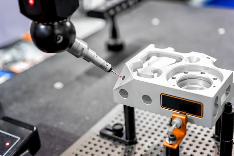
Coordinate Measuring Machine (CMM)
These machines provide high accuracy when it comes to measurements. Usually, machine shops with CNC machines will have a coordinate measuring machine that measures the parts and does all calculations digitally.
This is the most accurate way of measuring true position. The machine contains a ball at the end of a robotic arm. We guide the ball to the feature we need to measure. It then traces the feature and converts the motion into the feature’s profile using the embedded software.
The measurement method can be a bit confusing. And so, we have noted down the general steps that can be of help. We follow the following steps when measuring using a CMM.
Measure your datums
Check the print and locate your datums. For example, say A is a datum surface. Datum B is a datum axis, and C is a datum origin.
Align the part
Level the plane. Rotate to the line and set the origin as the C datum.
Measure features
Identify the dimension calling out the true position and measure it.
Dimension position
Now, click on Dimension and select the position. Then report it.
In case you are using feature control frames, you must define the datums in the editor prior to picking the features you want to report.
Special calliper
We can use a special set of callipers known as the centre distance digital calliper to measure the position. This calliper can measure the centre distance between two holes or step holes. They can measure a range of hole centre sizes.
We can use it for step as well as external measurement. They are easy to use with locking features, fine adjustment, and data presetting functions.
Fixed functional gauge
This is probably the fastest way to measure true position. We generally see its use in high volume manufacturing due to its efficiency. A functional gauge measures position only and not the feature size.
For example, for a workpiece with a hole, the gauge would be a block with a protruding pin at the true position of the hole and other features to align to the datums. If the pin can enter the hole when the gauge is in line with the datum, we accept the part. The feature size has to be measured separately.
