

The 2009 edition of ASME Section Y14.5 defines 14 geometric tolerances in GD&T. The manufacturing industry uses these tolerances to convey manufacturing intent from the designers to the manufacturers. GD&T helps us to inspect, control and measure the various features of a machine part.
The 14 geometric tolerances are classified into 5 main groups – form, location, profile, orientation and layout. Symmetry is one of the three tolerances under location control (the other two being true position and concentricity).
As the name suggests, it controls the symmetry of part features such as tapers, holes, chamfers, curves, etc. This may not be required in general applications. However, in special applications where balance and equidistant loading is of great concern (high-speed applications), symmetry becomes increasingly important.
What is Symmetry?
GD&T symmetry is a 3D tolerance that ensures that part features are symmetrical about a datum plane. The callout defines a central plane and creates a tolerance zone around it.
The GD&T symmetry callout ensures symmetry control by checking the distance between any two corresponding points on either side of the datum plane and calculating their median points. These median points must lie near the datum plane and be within the symmetry tolerance zone specified in the feature control frame.
Theoretically, the inspector must check all the median points and find them within the tolerance zone. However, for practical purposes, fewer points at different cross-sections are inspected. The remaining median positions are interpolated to achieve the median plane.
Symmetry Tolerance Zone
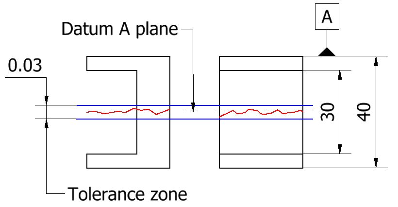 The symmetry tolerance consists of two parallel planes, one on each side of the datum center plane. The distance between the two parallel surfaces is the tolerance limit for the callout. For instance, if the tolerance limit is set at 0.03 mm, the two planes will be at a distance of 0.015 mm on either side of the datum plane. This type of zone is the default tolerance zone type in GD&T. It is also sometimes known as the total wide tolerance zone.
All the points on the median plane must lie in the volume between the two planes of the tolerance zone for approval.
Symmetry vs Other Callouts
The GD&T symmetry callout is a type of location control. It ensures that two features are at their proper locations when checked against the datum plane. Other location controls can also perform the same job, although using a different method and tolerance zone type. The symmetry tolerance is comparable to concentricity and true position in terms of what they can achieve.
Symmetry and Concentricity
The concentricity callout controls the concentricity of cylindrical surfaces whereas symmetry controls are typically applied to any non-cylindrical surface. Many refer to concentricity as the circular version of symmetry. ASME Y14.5M-1994, 5.14 states that: “…symmetry and concentricity controls are the same concept, except as applied to different part configurations.”
GD&T symmetry controls the location of two features by establishing a datum plane. The concentricity symbol, on the other hand, checks the concentricity by establishing a central datum axis. It then measures the spread of actual centers of cylindrical cross-sections; and if they are within the cylindrical tolerance zone around the ideal datum axis. Concentricity derives an actual central axis instead of a median plane.
Both symmetry and concentricity are incredibly difficult to measure. For accurate measurements, a coordinate measuring machine (CMM) is a must.
Symmetry and True Position
Symmetry and true position can both be used to define the ideal location for a part feature. They may even be used interchangeably in some situations. However, true position is far more versatile compared to symmetry. It can do everything symmetry can do but the opposite is not true.
The true position callout can establish a total wide tolerance zone as well as a circular zone. This increases the range of features that can be controlled by it. True position allows for bonus tolerances, whereas symmetry does not. Symmetry also does not allow datum feature shift and projected tolerance zone, both of which are possible with true position.
Another difference is that true position can be called Relative to Feature Size (RFS), or with Least/Maximum Material Condition (LMC/MMC). Symmetry is always applied RFS.
- Personal account manager
- Quality assurance
- Payment terms for companies
- On-time delivery by Fractory
Symmetry Feature Control Frame
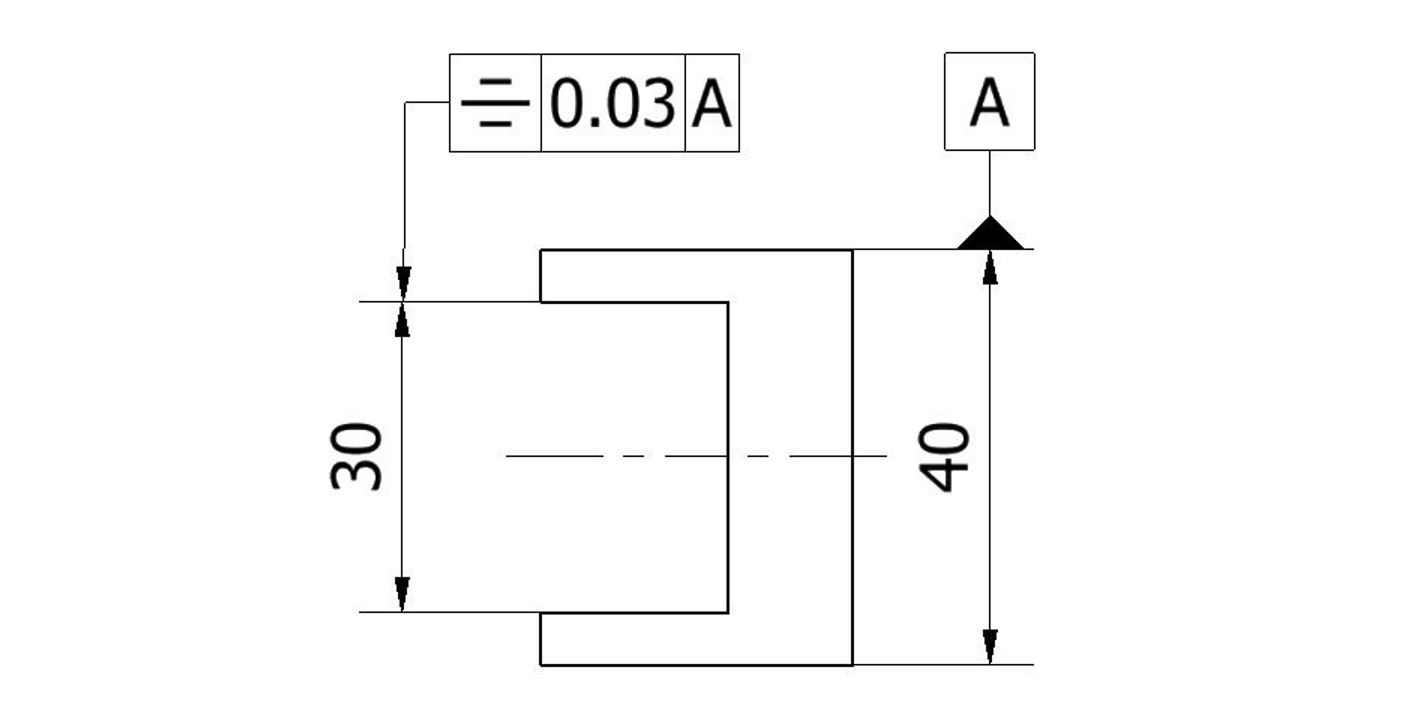
The feature control frame (FCF) for symmetry is one of the easiest to understand and use. On the drawing, the FCF is connected to the feature using a leader arrow. It points to the feature’s surface or its extension line.
The FCF gives all the required information about a callout using a set standard. A general FCF can be divided into three main blocks:
- Geometric tolerance block
- Feature tolerance block
- Datum block
Geometric tolerance block
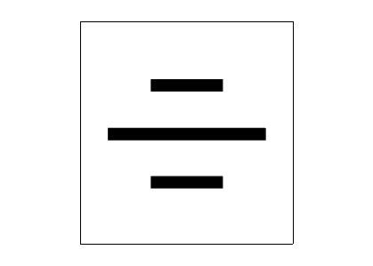
This block gives information about the geometric tolerance applied to the feature. It houses the symbol for the callout. The GD&T symmetry symbol consists of three horizontal lines on top of each other, with the middle line being slightly longer than the other two. The middle line represents the datum plane while the other two represent a feature subjected to the symmetry requirement.
Feature tolerance block
This block gives information about the type of tolerance zone, the tolerance limit and material condition modifiers, if any. The tolerance zone for symmetry is a total wide tolerance zone. No symbol is required as it is the default zone type.
The tolerance limit represents the distance between the two parallel planes. The lower the number, the tighter the tolerance.
The symmetry callout is always applied RFS, neither MMC nor LMC applies here. RFS is the default condition and does not require a symbol.
Datum block
The datum block houses the datum axis, points or planes that act as references for callouts. The symmetry callout requires a datum that will act as the reference plane for the measurement. The tolerance zone is placed evenly on either side of this plane. Measurements are taken across this plane during an inspection. This datum plane’s name is placed in the datum block.
How to Measure Symmetry
Among all the GD&T callouts, symmetry is one of the more difficult callouts to measure. The median points that must lie within the tolerance zone are a derived feature and there are no actual surfaces readily available for measurement. The symmetry symbol requires the calculation of these median points along with the feature under symmetry control. Such calculations require a lot of time and a skilled operator.
There are two main ways in which symmetry tolerance can be measured.
- Using a caliper or a micrometer
- Using a coordinate measuring machine
Using a caliper or a micrometer
It is possible to measure symmetry with an analog caliper or micrometer in some simpler cases. However, the operator’s skill and the instrument error can affect the accuracy of such measurements and thus it’s not generally recommended.
Different instrument designs are available for different form and location measurements. They can measure the size effectively but may not be as accurate when verifying the form. Another disadvantage is that this method requires manual recording of measurements.
Using a coordinate measuring machine
This is the most common method of measuring symmetry. A coordinate measuring machine (CMM) can plot all the median points by just bringing the stylus into contact with the opposing points. This method provides comparatively greater accuracy when compared to a caliper or a micrometer.
Initially, the CMM is set up to establish the theoretical center plane. Then, both symmetrical sides are measured using the CMM stylus to calculate where the median points fall. The positions of all the median points along the feature’s length are compared with the datum plane. The inspectors approve the part as long as no median point exceeds the tolerance limits around the datum plane.
The CMM records the measurements. Although this method requires less from the operators it is still relatively complex to achieve accurate results.
Uses of Symmetry
Symmetry finds use in very specific applications where there is a need for even load or form distribution. Symmetry is preferred for:
- High-speed applications where static and dynamic balancing is of great concern
- Machine elements under heavy load to prevent uneven wear
- Fluctuating loads to prevent fatigue failure due to disproportionate loading
Wherever possible, manufacturers avoid the use of symmetry tolerance as it is a difficult and expensive callout to measure.
Important Points to Remember
- It is worth noting that the symmetry callout has been removed from the 2018 edition of ASME Y14.5-2018, as it can be replaced easily by true position. Symmetry was in the 1994 and 2009 editions which are still predominantly used in the industry today.
- Straightness and parallelism can also replace symmetry in some instances.
