

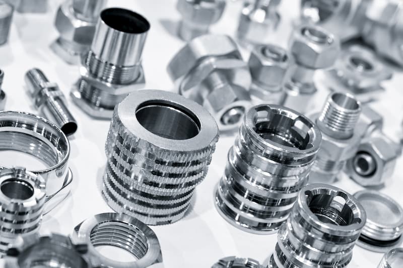
Computer Numerical Control (popularly known as CNC) machining refers to the use of computer programming and electromechanical devices to automate metal parts (and nonmetals) machining as needed. A CNC machine carries out all the operations on the workpiece based on the program to give us the final product.
There Is Always Variation
While CNC machining services are highly accurate when it comes to product dimensions, they are not perfect. The final measurements between any two parts made using the same manufacturing process even on the same CNC machine are always off by a small amount. It is impossible to create identical parts of the same exact dimensions no matter which CNC machine we select.
This difference in final measurements between two parts made from the same CNC machine is accounted for by setting up a standard tolerance limit. The tolerance limit defines the maximum allowable difference between corresponding dimensions of the two parts.
For CNC machining, the standard tolerance limit is set around +/-.005” (0.127 mm). For reference, the thickness of a human hair is 0.002” (0.05 mm).
The standard tolerance limit is a small number and in most cases, such a small difference between two parts that perform the same function may not even matter. For the remaining cases where small dimension variations can affect the part’s performance, tighter tolerances can be maintained.
Common Tolerances in CNC Machining
Engineering tolerances are a necessary requirement when defining product measurements. Unless the customer specifies any certain tolerances, the parts will usually be made according to a general tolerance grade.
Thus, it is in the designer’s interest to define part tolerances for the appropriate features before handing it over for CNC machining. This ensures customer satisfaction and reduces retooling costs for the CNC machine shop, should anything not accord to the requirements.
By appropriate features, we mean that it is not necessary to define tolerance for every dimension. This has a rather opposite effect actually because adding requirements to each measurement will make for a very costly part.
We usually define it for only those features in a part that mate with other parts. When we do this, it ensures that the components fit well in an assembly and work as expected.
The various types of tolerances applicable to machined parts are:
General Tolerances
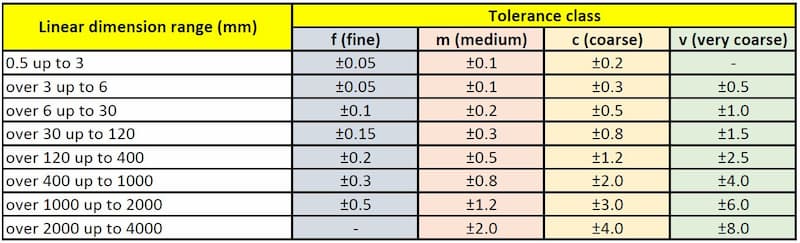
General tolerances may be defined for linear or angular measurements, as well as for chamfers or other rounded parts. These tolerances specify standard tolerances for 4 different classes based on their range for a part dimension.
These classes are arranged into a chart that separates the different tolerance limits as very coarse (v), coarse (c), medium (m), and fine (f).
The range for each tolerance limit for a particular dimension bracket is based on International Standards (EN 20286, JIS B 0401, ISO 286, ISO 1829, ISO 2768, ANSI B4.1, ANSI B4.2).
Limit Tolerances
We express the limit tolerance as a minimum and maximum permissible value for a dimension. The corresponding dimension of the manufactured components should lie between these two points for use in the assembly.
For example, if the limit tolerance for a dimension is defined as 12…12.5 mm, the final value must lie between these two boundaries.
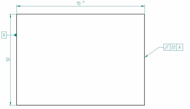
Unilateral Tolerances
In unilateral tolerance, we define the range of values in one direction only. In other words, we allow deviation on only one side of the nominal value.
Consider a shaft of diameter 70mm that needs to fit into a hole of the same size. If the shaft’s diameter exceeds 70mm even by a small amount, it will not fit into the hole.
Thus, we cannot use the shafts manufactured with a diameter greater than 70 mm. This would increase wastage and turnaround time.
To prevent this, we use unilateral tolerances for such parts. If we can allow a maximum deviation of 0.05 mm, we will set the tolerance range for this shaft as 70 +0.00 /-0.05 mm. This range gives us a maximum and minimum permissible value of shaft diameter as 70.00 mm and 69.95 mm respectively.
An advantage of using unilateral tolerance is the ease with which we can inspect it. Since the dimensions vary only on one side with the upper value fixed, we can standardise a go gauge to increase the speed and ease of inspection.
Bilateral Tolerances
In bilateral tolerance, the final measurements of a part can vary on either side of the nominal value or true profile. For example, a bilateral tolerance of 30 +0.05/-0.05 mm refers to a minimum and maximum value of 30.05 mm and 29.95 mm respectively where 30 mm is the nominal value.
GD&T
Geometric dimensioning & tolerancing (GD&T) is a step up from regular dimension tolerances. Besides ensuring that the final value remains within defined boundaries, it defines further characteristics of the dimension such as its concentricity, flatness, and true position.
The final dimension must have these predefined characteristics to pass the inspection.
While the other tolerance types are widespread everywhere, GD&T is especially relevant for CNC machining. These parts often have very high requirements and GD&T allows possibilities to ensure dimensional accuracy for a variety of features.
- Personal account manager
- Quality assurance
- Payment terms for companies
- On-time delivery by Fractory
CNC Tolerancing Basics
Now that we understand why we need tolerance limits and its various types, let’s look at why selecting the right limit is important. The appropriate tolerance limit ensures flawless part performance without unnecessarily high costs.
Choosing a tighter tolerance than necessary, however, has a few disadvantages.
So let’s see what should be kept in mind when choosing the tolerances.
High Costs for Tight Requirements
For several reasons, aiming for tighter tolerances considerably affects machining costs as well as the turnaround time. A tighter limit requires more time and labour.
It also increases the likelihood of a part falling outside the range and being scrapped. The machine will need special jigs and fixtures to achieve these limits. Finally, very tight tolerances will need special measurement tools for quality control.
Choice of Manufacturing Methods
The tolerances set by the designer dictate which manufacturing processes are more suitable to achieve them. As tolerances become finer, fewer CNC machines will be able to complete the job satisfactorily as they differ in their capabilities when it comes to precision.
The component may require further operations such as grinding and lapping to achieve the desired tolerances. But Swiss machining, for example, is able to produce turned parts with incredibly tight tolerances that in most cases do not need any secondary finishing processes. This is economically feasible at higher volumes though.
Tolerances Depend on the Material
The choice of material decides the ability of a manufacturing process to accomplish a certain tolerance range. The difference in material properties can significantly affect the final values.
Soft workpieces are hard to fix as they keep bending when they come in contact with the cutting tool.
On the other hand, an abrasive material can wear out the cutting tool and make it harder to achieve the preferred value. Phenolics such as GP 11, GP 03, or any glass laminates are examples of such materials.
The exposure to friction heat during the cutting operation can cause some materials (e.g. plastic parts) to distort. Thus, a material type may be incompatible with a manufacturing process when trying to achieve tight tolerances.
Inspection
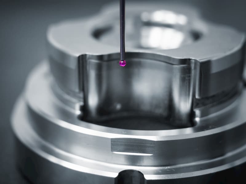
The finer the tolerances, the harder and more time consuming it is to inspect them. They demand better measurement tools and inspection methods. This increases the manufacturing costs of the component.
For example, chatter marks can form due to vibration during the machining process. We can check these marks visually but to obtain important information such as the length and depth of these marks, we need advanced inspection equipment. These marks (especially when it comes to finer tolerances) can be disruptive, creating noise and vibration in the assembly.
Conclusion
CNC turning and milling are known for the high quality and precision they can provide. At the same time, engineers need to be wary of a few important aspects when choosing the requirements and not go over the top with the demands.
Educating yourself about material properties and keeping the project’s working environment in mind helps with decision-making.
