

CNC turning is one of the central methods of manufacturing. It can produce cylindrical parts with various contours.
In machine building, you cannot bypass shafts to transmit power from the motor to the moving parts. Shafts, of course, require turning. But CNC turning and boring find a lot of use in various industries to produce usually axi-symmetric parts.
What Is Turning?
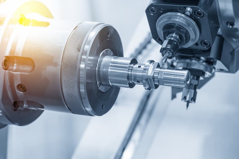
Turning is a subtractive machining process that uses a cutting tool to remove material for creating cylindrical parts. The tool itself moves along the axis of the machined part while the part is rotating, creating a helical toolpath.
The term turning refers to producing parts by cutting operations on the external surface. The opposite of turning is boring, whereby lathe machines are used for creating hollow parts, for example.
The lathe machine is historically one of the earliest of its kind for producing parts in a semi-automated fashion. Today, most companies provide CNC turning services. This means that the process is largely automated from start to finish.
CNC refers to computer numerical control, meaning that computerised systems take control of the machinery. The input is digital code. This controls all the tool movements and speed for spinning as well as other supporting actions like the use of coolant.
CNC Turning Process
What does the turning process actually comprise of? While the cutting itself is pretty straightforward, we are going to look at the whole sequence here which actually starts from creating a CAD file.
The steps of the process are:
- Creating a digital representation of the part in CAD
- Creating the machining code from the CAD files
- CNC lathe setup
- Manufacturing of the turned parts
CAD design & G code
The first 2 steps can be seen as separate or going hand-in-hand. One way is to just use a CAD program to create the files and send them into production. The manufacturing engineer will then create the G code and the M code for the machining job.
ARVE error: url: https://www.googleapis.com/youtube/v3/videos?part=snippet%2Cstatistics&id=6JAZKjnnKvE&key=AIzaSyAQ7WFzTAUrOX-FjsIrFS3JwZBFzgIvloc Status code 200 expected but was 403.
Another way is to just use CAD-CAM software which lets the design engineer test the producibility of the part. The powerful simulation tools can visualise the whole process from raw material to the final product, even using the input regarding finishing requirements.
Lastly, there is also a manual way for creating the code. For example, you cannot automatically generate the code from a 2D drawing, leaving you with 2 options – either writing the code manually or producing a 3D model first.
Even the powerful CAM programs may not always get everything spot-on, so checking the coded instructions is recommended.
Lathe setup
Next comes the machine setup. This is where the machine operator’s role becomes evident. Although contemporary CNC lathes do most of the work automatically, the operator still plays a vital part.
Steps for setting up a CNC turning centre:
- Making sure the power is off. CNC machining can be dangerous, so extra care is necessary and checking the power switch is the basis for that.
- Securing the part into the chuck. The chuck holds the part during the whole process. Improper loading can both pose dangers as well as result in a finished part with the wrong dimensions.
- Loading the tool turret. Turning comprises of many steps, so be sure to choose the right tooling for a certain finish. The turret can hold many tools at once for a seamless operation from start to finish.
- Calibration. Both the tool and part have to be set up in the right way. If anything is off, the result will not meet the demands.
- Upload the program. The last step before pushing the start button is uploading the code to the CNC machine.
Part production

ARVE error: url: https://www.googleapis.com/youtube/v3/videos?part=snippet%2Cstatistics&id=kicepCM4eb4&key=AIzaSyAQ7WFzTAUrOX-FjsIrFS3JwZBFzgIvloc Status code 200 expected but was 403.
The easiest way to get the essence of manufacturing is just watching the video above. You can see both turning and boring in this video. The raw material, as evident, is not a round bar which is the most common option. Rather, a hexagonal profile is a more efficient way to go here to avoid CNC milling later on.
Depending on the complexity of the part, one or more cycles may be necessary. Cycle time calculations determine the final time spent which is necessary for cost calculations. A turning cycle time comprises of:
- Loading time. We already described it as part of the setup but a cycle may necessitate for another way of loading the part into the machinery.
- Cutting time. The time it requires depends on the cut depth and feed rate.
- Idle time. Idles times refer to anything that is not cutting, i.e. movement of tools to and from the piece, changing the settings of the lathe, etc.
- Tool lifetime. Although each cycle does not wear out the tool completely, the cutting time will be taken into account vs the overall lifetime of a tool to include it in the final cost.
- Personal account manager
- Quality assurance
- Payment terms for companies
- On-time delivery by Fractory
Turning Parameters
The parameters of CNC turning depend on various aspects. These include the material of the part and tool, tool size, finishing requirements, etc.
The main parameters for CNC turning are:
- Spindle speed. The unit is rotations per minute (rpm) and it shows the rotational speed of the spindle (N), thus also the workpiece. The spindle speed is in direct correlation with the cutting speed which also takes the diameter into account. Therefore, the spindle speed should vary to maintain a constant cutting speed if the diameter changes considerably.
- Workpiece diameter. As said, this plays an important role in arriving at the right cutting speed. The symbol is D and the unit is mm.
- Cutting speed. The equation for calculating the cutting speed is V=πDN/1000. It shows the relative speed of the workpiece to the cutting tool.
- Feed rate. The unit is mm/rev and the symbol is s. Cutting feed shows the distance the cutting tool moves per one turn of the workpiece. The distance is measured axially.
- Axial cut depth. Pretty self-explanatory as it shows the depth of a cut in the axial direction. It is the primary parameter for facing operations. A higher feed rate puts more pressure on the cutting tool, shortening its lifetime.
- Radial cut depth. The opposite of axial cut, this parameter shows the depth of cutting perpendicular to the axis. Again, lower feed rates help to lengthen the lifetime of tools and secure a better finish.
CNC Lathe Main Parts
Now, let’s see the main components of a turning centre.
Headstock
The headstock of a CNC lathe makes up the front section of the machine. This is where the driving motor is along the mechanisms to power the spindle.
The chuck or collet attaches to the spindle. Either of them, in turn, holds the workpiece during the turning operation.
Chuck and collet
The chuck grips the machined part by its jaws. It attaches directly to the spindle but is replaceable, so different-sized parts can be machined.
Collet is basically a smaller version of a chuck. The part size suitable for collets is up to 60 mm. They provide a better grip for small parts.
Tailstock
The other end of a CNC turning centre. A tailstock attaches directly to the bed and its purpose is to provide support for longer workpieces. The tailstock quill provides support by hydraulic force.
The driving force still comes from the spindle and the tailstock just runs with the part. Using a tailstock is not suitable when face turning is necessary, as it will be in the way.
Lathe bed
The bed is just a base plate that rests on the table, supporting other machine parts. The carriage runs over the bed which is heat-treated to withstand the machining effects.
Carriage
The carriage rests on ways for sliding alongside the spinning workpiece. It holds the tools, allowing for the cutting process to take place.
Turret
Newer machines usually come with a turret that replaces the carriage. They can hold more tools at the same time, making the switching from one operation to the other less time-consuming.

ARVE error: url: https://www.googleapis.com/youtube/v3/videos?part=snippet%2Cstatistics&id=PLBc81w2eVc&key=AIzaSyAQ7WFzTAUrOX-FjsIrFS3JwZBFzgIvloc Status code 200 expected but was 403.
CNC machining centres may come with live tooling. While single-point cutting tools are suitable for most turning operations, live tooling refers to mills, drills and other tools that have their own power. This allows the creation of keyways or holes perpendicular to the part axis without using any other machinery in the process.
Control panel
This is where computer numerical control kicks in. The brains of CNC turning machines are just behind the panel. The panel itself allows the operator to adjust the program and start it.
Types of Lathes
A wide range of CNC lathes offers a variety of possibilities. Each comes with a unique set of features while some are more automated than others. So everything has its place, whether a few one-off jobs at a small machine shop or batch production for larger quantities.
Bench lathe
The name suggests that it is small enough to attach it to a tailored workbench. They are, still, larger than micro or mini-lathes.
A great way to perform general machining or a special tool for a hobbyist, it can perform many of the necessary operations. A bench lathe requires a skilful machinist as there is little to no automation, putting more responsibility on the operator.
Engine lathe
The most common type of lathe. The name has stuck since the 19th century when a steam engine made this specimen stand out in the midst of other manual lathes. Since the beginning of the 20th century, a conversion towards electric motors got on its way.
Using gearboxes in the headstock made the choice of spindle speed easy and high-speed machine tools became the norm. The new-found power pushed the industry to invent new ways of increasing the tool life. Replaceable carbide inserts were just the way to do that.
As a result, engine lathes can perform CNC machining at high speeds, leading to shortened production times and lower costs. Although still common in workshops, engine lathes laid the foundation for improved performance and the automation of machining.
Toolroom lathe
Similar to an engine lathe with a few differences. Usually, they are smaller in size to fit in tighter spaces. At the same time, there are some extra capabilities available, making it rather a higher-end machine, not one suitable for entry-level.
The toolroom lathes include chuck and collets, taper attachment among other things that, for example, simpler bench lathes do not have.
Turret and capstan lathes
These types of lathes are pretty much interchangeable based on the operations they can perform. As you learned before, the use of a turret opens up a wide range of automation possibilities. Also, many more operations can be performed on a single workbench.
From turning and boring to drilling, threading, and making keyways, everything is possible without a change of tools. The turret holds all the necessary tooling at once, so you can easily go from one process to the next.
Coupling CNC with fewer manual tasks, and producing almost identical machined parts in batches is a strong point of this type of lathe.
Swiss-type lathe
Swiss lathes operate with incredibly small tolerances at shorter cycle times than conventional lathes, making them an attractive option for manufacturing complex parts at larger volumes.
Swiss machines have a moving headstock, allowing the workpiece to be repositioned along the z-axis as it undergoes the machining process. In other words, to cut lengthwise along the part, the tools will move in and the material itself will move back and forth along the z-axis. This allows all the work to be done on the material near the guide bushing where it is more rigid, eliminating deflection and vibration.
Multispindle lathe
The multispindle lathe has more than a single spindle. The additional capacity is especially suitable for high-volume production.
Setting up the machine requires quite a lot of time, so the combination of this and the high cost of the machine itself needs high-volume production to pay it off. When applying this, they can create similar parts with high precision, low cycle times and very little manual work aside from the initial setup.
So large-batch manufacturing can considerably lower the cost of CNC machining.
CNC lathe
Although some of the aforementioned types also accommodate a CNC system, the CNC lathe deserves a separate mention.
CNC refers to computer numerical control, which takes care of operating the machine to some extent. This depends on the specific machinery, as they can be fully or semi-automatic.
Semi-automatic CNC lathes need a little more work from the machine operator whereas fully automatic centres are able to do everything from mounting the workpieces to changing the tools.
The highly accurate CNC machines are the best the contemporary industry has to offer. Digitising the whole process from the creation of CAD to a fully finished part is possible. Also, the enclosures significantly reduce the risk during machining, as the workers are not really exposed to any moving components, controlling anything necessary from a computer screen.
Axis Identification in CNC Lathe
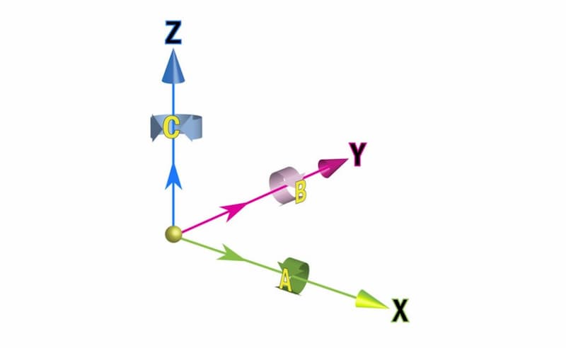
The most common way of identifying the axes on a traditional CNC lathe machine goes like this:
The Z axis runs parallel to the axis on the workpiece. So the tool can move along the side of the material while the part revolves around the Z-axis (C). Movement along the Z-axis determines the length of the job.
As you can see, the X-axis is perpendicular to the Z-axis. Therefore, the tool can move to and from the piece on the X-axis to determine the diameter of the part.
Different Operations
CNC turning is suitable for performing a wide range of operations. We have named some of them already but let’s take a closer look now to bring clarity to the capabilities of lathe machines.

ARVE error: url: https://www.googleapis.com/youtube/v3/videos?part=snippet%2Cstatistics&id=-J3wN1ruDZM&key=AIzaSyAQ7WFzTAUrOX-FjsIrFS3JwZBFzgIvloc Status code 200 expected but was 403.
Turning
The most common operation. A single-point tool moves along the axis of the workpiece to remove material from the part surface. It can produce various contours, like steps, tapers, etc. Normally, a few passes are necessary to reach the end result.
Because of the high precision attainable with turning, the limits and fits are usually chosen on a hole-basis system. Reaching the tight tolerances with CNC turning is easier than doing the same when drilling a hole.
Facing
Facing removes a layer of material from the end of the workpiece. Usually, the purpose is to arrive at a desirable surface finish. As the cutting depth does not have to be very deep, a single pass can perform that. The movement of the cutting tool is perpendicular to the spinning axis.
Grooving
Similarly to facing, the tool moves perpendicularly to the spinning axis. Instead of cutting the end of the workpiece, groove cutting is performed somewhere along the side. A single-point turning tool can perform the cut in a single pass if the width of the cut is identical to the tool’s width. Otherwise, multiple cuts are necessary.
Parting
Parting is also known as cutting off. The latter term describes this turning operation in a very straightforward manner. The process itself looks like grooving but the cutting tool will reach the axis of the part. Meaning that it cuts off a segment of the part.
Threading
Here we are still talking about an external operation. So threading is used to cut threads on the surface of a part. The specifics of the thread can be configured and reaching the final outcome may require several passes.
Drilling
The first internal operation on this list. When talking about traditional turning, drilling can be performed on the end of the workpiece, right on the axis. As the part is spinning anyway, the tool bit can remain stationary. Newer CNC lathe centres can use live tooling to produce perpendicular holes on the sides or elsewhere.
Boring
The opposite of turning. All the same features can be performed, just on the inner surface. Boring requires some drilling first, to make room for inserting the tools into the workpiece. From there, enlarging the hole with single-point cutters is possible, along with adding steps, chamfers, etc.
Reaming
Reaming is a machining process whereby a multi-toothed fluted tool enters an existing hole to make it larger. The outcome has a very smooth surface finish with tight engineering tolerances. The operation itself looks similar to drilling from the outset.
Tapping
Similarly to reaming, requires a previously drilled hole. A tap enters the existing hole to give it an internal thread. Requirements for the existing hole are related to the thread size – it must be close to the tip of the thread teeth.
Suitable Materials for Turning
Besides the types of lathes we described earlier, there are other categories based on the suitable materials for a lathe. Wood, metal and glass all have different lathes because they all need some specific qualities, as well as cutting speeds.
When it comes to material profile, square, round, hexagonal, etc. are welcome. As one of the videos above shows, having a profile other than round can come in handy if the final part is not round at all sections.
Suitable materials for turning include:
- Metal
- Wood
- Glass
- Plastic
- Wax, etc.
Here at Fractory, we provide services for metal turning.
Conclusion
Turning is one of the pillars of the manufacturing industry. Getting precise results for axisymmetric parts is best done with that fabrication method. The flexibility and production capacity allows large-batch manufacturing with almost identical outcomes.
Today, large CNC machining centres may include both CNC milling and turning capabilities. Milling machines add an extra layer of capabilities, making these machines really powerful for creating intricate parts.
