

The GD&T standards in ASME Y14.5-2009 define fourteen types of geometric tolerances. These fourteen geometric tolerances are divided into 5 main types of geometric control. These are form, location, orientation, profile and runout.
Form controls determine the form of individual part features. In this article, we shall learn about cylindricity tolerance which is one of the four types of controls in the form category (the other three being straightness, flatness and circularity).
As the name suggests, designers and manufacturers use cylindricity to create accurate cylindrical parts.
What Is Cylindricity?
The cylindricity control is a GD&T tolerance from the form control group and guarantees a part’s cylindric shape by determining the two key aspects of roundness and axis straightness.
Many cylindrical parts that fit into a tight assembly must be “cylindrical enough” for a good fit. This is especially true for parts that fit into long, tight bores where the circularity, straightness, and taper of the cylindrical part must be within tight specifications.
Take the example of a pin that needs to pass through a hole with tight diametral tolerance. Even if the pin is perfectly round (good circularity), a small deviation from desired straightness (bend along the length) will prevent it from passing through the hole.
The cylindricity callout specifies how close the cylindrical dimensions of an actual part need to be to an ideal cylinder.
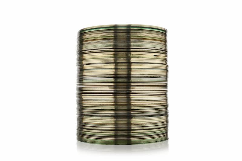
We can explain the working of the cylindricity callout by means of a disc stack. The cylindricity control, besides checking the circularity of each disc, also checks that the discs are stacked straight.
If even one of the discs deviates too much in size or roundness compared to the others or it shifts to one side more than allowed, the whole stack would fail to adhere to the tolerance limits.
Cylindricity Tolerance Zone
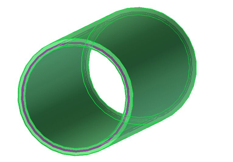
The cylindricity tolerance zone is represented by two concentric cylinders. These cylinders run along the entire length of the curved surface, one on the inside and the other on the outside, creating a perfect cylindrical boundary around the part’s entire surface.
The cylindricity tolerance zone is the volume enclosed by the radial separation between these two concentric cylinders. The difference in their sizes is the applied cylindrical tolerance limits. Thus, the zone is such that the entire surface of the part is constrained.
The common axis of the concentric cylinders in the tolerance zone coincides with the axis of the cylindrical part. All points of the surface under control must lie within the zone between these two concentric cylinders for approval.
Cylindricity vs Other Callouts
Each callout in GD&T has specific applications where it will work just perfectly. Before applying them, a designer considers factors such as the desired degree of accuracy, tolerance limit and ease of measurement.
Cylindricity bears certain similarities to other callouts. This can be a source of confusion for many engineers. It is necessary to have a good understanding of the similarities and differences between their characteristics and how we apply them.
Two callouts that function somewhat similar to cylindricity are circularity and total runout. Let’s compare them with cylindricity.
Cylindricity vs circularity
Cylindricity is to circularity what flatness is to straightness. In both cases, an additional dimension is introduced.
While circularity applies to one cross-section at a time as it has a flat (2D) circular tolerance zone, the cylindricity tolerance zone covers all the cross-sections at once (3D). Thus, cylindricity controls the entire surface as opposed to a single cross-section in circularity.
It is as though the circularity tolerance zone is stretched in the third dimension along the full length of the cylindrical part. Hence, cylindricity is also sometimes appropriately referred to as the 3D version of circularity.
Cylindricity can also be understood as a combination of circularity and straightness callout. Consider the previous example of a disc stack.
Circularity would only be concerned with each disc being perfectly round or having good circularity, whereas cylindricity control would also consider the straightness of the whole stack. So when the taper of a cylindrical part in an application does not bear much importance, it is better (easier to check and cheaper to ensure) to use circularity.
However, when a perfect cylinder with good circularity and taper control (near-perfectly straight) is needed, cylindricity is the way forward.
Cylindricity vs total runout
Cylindricity control and total runout control are pretty much the same feature characteristics with some minor differences.
Similar to cylindricity control, total runout is also a 3D callout that controls the entire surface of the part. Total runout is most commonly applied to cylinders but may be used for other features on rare occasions.
A key difference between the two is that total runout, when controlling a cylindrical feature, is concerned with where the centre of each cross-section lies with respect to its ideal position. Cylindricity, on the other hand, forms direct boundaries around the entire surface of the cylinder without any concern for the position of each cross-section’s centre.
The most obvious difference between the two, however, is the need for a datum feature. Total runout cannot be defined without a datum feature but cylindricity can.
This means that total runout can control orientation, location, and form (only if the total runout tolerance is tighter than size tolerance) whereas cylindricity only controls the form
Just like all other form controls, cylindricity does not use a datum feature and controls only the shape while needing other controls to control size. Even using a tighter cylindricity tolerance limit will not control the size.
- Personal account manager
- Quality assurance
- Payment terms for companies
- On-time delivery by Fractory
Cylindricity Feature Control Frame
The feature control frame is a means to describe how a geometrical control applies to a feature. It uses standard layout and symbols to convey the tolerance type, tolerance value, specific conditions and reference points to give complete information about the applied callout.
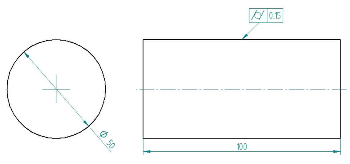
The feature control frame for cylindricity, compared to other GD&T callouts, is quite simple and easy to apply. It points to a feature on paper by means of an arrow known as the leader arrow/line. This arrow indicates the feature under control. If it points to an axis, the axis is under control. If it points to a surface, the callout controls the surface.
As cylindricity is always applied to an individual surface, the leader arrow/line always points to a surface. It may point towards the surface or its extension line in the rectangular view (when viewing the cylinder from the front) or the circular view (when viewing the cylinder from the side).
A general feature control frame consists of three blocks known as:
- Geometric characteristic block
- Feature tolerance block
- Datum block
Geometric characteristic block
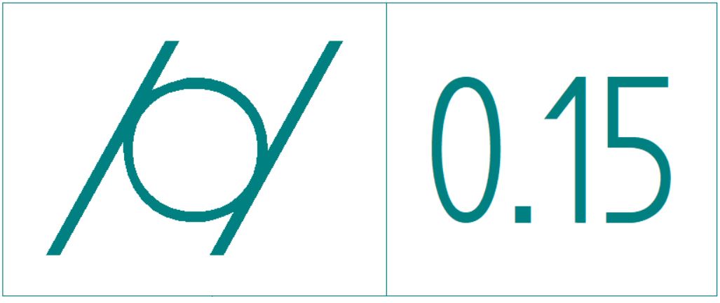
The geometric characteristic block houses the symbol for the type of geometric tolerance in a feature control frame. The cylindricity symbol is a circle enclosed by parallel lines on each side. When writing, it is often written as /o/.
Feature tolerance block
The feature tolerance block gives information about the type of tolerance zone, the tolerance value and material condition modifiers if any.
In the case of cylindricity, the zone is not a diameter tolerance zone. Hence, there is no diameter symbol in this block. The cylindricity tolerance zone is similar to flatness – if the flatness tolerance zone was wrapped around the surface of the cylinder.
So this block states the tolerance value for the feature. This value is the radial separation between the two coaxial cylinders of the tolerance zone.
As for the material condition modifiers, they do not apply to cylindricity (both MMC and LMC) as cylindricity is a form control. It does not control size. Therefore, Regardless of Feature Size or RFS applies to cylindricity at all times.
Datum block
The datum block holds any datum references that act as reference points for relationship geometrical controls. Cylindricity is a form control applied to the entire surface independent of any other feature.
Thus, it does not need a datum feature and so the feature control frame for cylindricity is complete without a datum block.
How to Measure Cylindricity
The cylindricity control finds less use compared to other form controls due to it being restricted to cylindrical parts. Depending on the tolerance value, it can also be difficult to measure.
From wobbling and vibration in high-speed applications to bearing and bushing failure, wrong measurements can cause a variety of problems in service. Thus, it is important to ensure that cylindricity is within specifications.
The cylindricity control also detects surface flaws such as pits or bumps that may otherwise go undetected.
Machinists use a variety of methods to measure/inspect cylindricity. Let’s take a look at some popular methods for measuring cylindricity.
Using a roundness measuring instrument
Roundness measuring instruments are used to measure cylindricity and circularity. To verify the accuracy of a cylindrical feature, we check for radial as well as longitudinal distortion in the cylinder.
In order to measure cylindricity error using a roundness measuring instrument, follow the steps below.
- Firmly secure the cylindrical part on the turntable. Ensure that the part rotates along its central axis.
- Put the measuring instrument’s probe or stylus in touch with the circular element. The range of the measuring instrument should be greater than the tolerance limit on the part.
- Turn the part using the turntable. Record the different values along the cross-section on a polar graph or analyze using a computer algorithm. In the case of a large part, the inspector can move the stylus instead of the part.
- Repeat a similar measurement at multiple points along the full length of the cylinder.
- For approval, the stylus’ movement range must be less than the specified tolerance value.
A roundness measuring instrument is great for measuring cylindricity but is limited by the fact that it can only measure circularity and cylindricity. When using it, great care must be taken to ensure that the turntable axis matches the feature axis for an accurate measurement.
Using a Coordinate Measuring Machine (CMM)

ARVE error: url: https://www.googleapis.com/youtube/v3/videos?part=snippet%2Cstatistics&id=ZS-hcpSqBik&key=AIzaSyAQ7WFzTAUrOX-FjsIrFS3JwZBFzgIvloc Status code 200 expected but was 403.
Many times, accurate cylindricity measurements will not be possible without a CMM. A CMM is far more capable of GD&T measurements compared to manual alternatives. An advantage of CMM is that besides cylindricity, it can measure a variety of other geometric tolerances.
To measure cylindricity error using a CMM follow the steps below.
- Select a cross-section and mark four or more points for point measurement.
- Use the CMM manually or by computer control and take measurements at the marked points of the circular element. The CMM stylus is extremely flexible and can take measurements from various angles for different points. These may also be plotted on a polar graph manually or using a computer algorithm.
- Repeat measurements at various points along the entire length of the cylindrical part for a complete cylindricity measurement.
- For approval, the total variation on CMM must be less than the tolerance amount.
CMM is a highly versatile measuring instrument. The use of CMM for cylindricity measurements provides high accuracy, reduced setup time and increased productivity.
Uses of Cylindricity
If precise circularity, taper, and straightness are important, cylindricity is the most suitable GD&T callout. The callout finds abundant use in mechanical and automotive applications.
The different parts that frequently use the cylindricity control are as follows:
● Shafts
● Pins
● Cylinder liners
● Bearings and bushings
● Hydraulic and pneumatic cylinders
● Regular and telescopic pipes
● Camshafts
All these parts often have shape constraints for a good fit. The cylindricity control can ensure that the shape of these parts corresponds to a near-ideal cylinder.
Important Points to Remember
● The cylindricity callout does not need a datum.
● The tolerance value for cylindricity cannot be greater than the tolerance value for size (diameter).
● The envelope boundary remains unaffected by the cylindricity tolerance.
● There is no symbol for diameter in the tolerance block of the FCF as the cylindricity callout does not control the axis but the entire surface profile.
● We cannot use the MMC or LMC condition modifiers with the cylindricity callout. Hence, there is no bonus tolerance associated with it.
● Cylindricity must be considered in a statistical tolerance stack as it controls the form of the entire surface.
● Normal tolerance stack does not need cylindricity to be included as per rule #1 of GD&T which states that the maximum envelope (boundary) for a FOS is its MMC. This means that the radial boundary in cylindricity cannot be greater than the maximum diametral tolerance.
