

ASME Y14.5-2009 classifies fourteen different types of geometric tolerances. These fourteen tolerances can be sorted into five broad groups, where each group represents the type of control they exercise on the different features. These five groups are form, location, orientation, profile and runout.
In engineering, runout refers to an error in the rotation about a central axis of rotating mechanical systems. Any kind of wobble or eccentric rotation can cause problems in the functioning of various machines and must be minimised as much as possible. The runout control helps us achieve that.
The runout group houses circular runout and total runout.
Like profile control, runout controls are combination controls as they affect multiple physical characteristics of a part such as its location, size and form.
But more on that later. Let us start with defining what total runout represents.
What is Total Runout?
Total runout is a composite tolerance that controls the location, orientation and cylindricity of the entire surface simultaneously. It does so by specifying a datum axis and rotating the part by 360 degrees.
Any peaks and valleys on the surface are observed with respect to the applied total runout tolerance zone. All points on the surface must lie within the tolerance zone, and the difference between the highest and the lowest point on the entire surface must be less than the applied tolerance limit.
In the case of cylindrical parts, besides controlling surface irregularities, total runout controls any axial variations in a part. Bends, if any, along the part length should not cause the part to breach the runout tolerance zone.

Let us understand how total runout works with the example of a coin stack.
Total runout ensures that all the coins in the stack are perfectly round. It also ensures that they are stacked perfectly straight and that none of them is jutting out along the length of the stack, and also that the stack is located at its defined position in the correct orientation.
This kind of tight control isn’t needed in all applications, but many parts could not function satisfactorily without such accuracy, especially in high-speed applications.
A second way to apply total runout is to measure the surface variations on a flat surface. Think of a solid cylindrical part with flat faces at each end. Total runout can control the flatness of the front face and ensure that it is perpendicular to the datum axis.
- Personal account manager
- Quality assurance
- Payment terms for companies
- On-time delivery by Fractory
Total Runout Tolerance Zone
The tolerance zone is of two types, depending on what type of surface total runout controls.
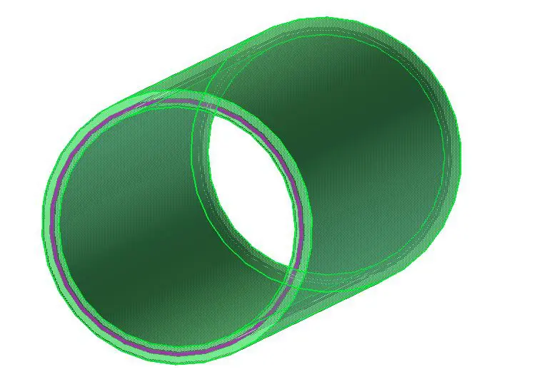
For a cylindrical part, the tolerance zone is a 3-dimensional cylindrical sleeve around the referenced surface. The inner and outer limit is marked by two coaxial cylinders whose central axes coincide with the specified datum axis.
When total runout is applied to a flat surface perpendicular to the central axis, the tolerance zone is made of two flat planes located on either side of the surface referenced in the feature control frame. All the surface elements must lie in the space between these planes for approval.
Total Runout vs Other Callouts
Total runout places many restrictions on the surface. These restrictions actually enable total runout to control multiple characteristics of a part. It may thus be used to replace individual callouts that control one attribute at a time.
This is highly beneficial as it eliminates the need to inspect each attribute with a different inspection method and replaces it with one standard method that measures the total runout of the part. Total runout controls the following attributes of a part at a time.
- Circularity
- Coaxiality
- Concentricity
- Straightness
- Cylindricity
- Surface taper
- Parallelism
- Angularity
- Perpendicularity
- Profile
- Flatness (when applied to a planar surface)
Thus, as a callout, total runout bears some similarity to many other GD&T callouts. Let’s explore these similarities as well as any differences between total runout and other callouts.
Total Runout vs Circular Runout
Circular runout and total runout bear the most resemblance to each other.
Circular runout, or as it is more popularly known, simply “runout”, is also a combinational control like total runout, controlling the location and orientation in addition to a part’s form. But there are some key differences between the two.
While circular runout controls a single cross-section at a time, total runout inspects the entire length of the cylindrical part simultaneously. It is the 3D version of circularity.
The runout tolerance can control a variety of surfaces such as cones, cylinders, and spheres, whereas total runout controls only cylindrical surfaces.
As compared to circular runout, a surface with a total runout control is more expensive and tougher to produce and inspect. Designers should, therefore, prefer circular runout if the application can function satisfactorily without cylindricity or flatness control.
Total Runout vs Cylindricity
Cylindricity combines circularity and straightness to measure how closely a part feature resembles a perfect cylinder. Any deviation in the form is expressed as increased cylindricity.
Cylindricity is applied to cylindrical parts only. The use of total runout for parts that are not cylindrical is highly unusual but possible. It may be used to measure flatness, as we already saw in the initial description.
The key difference lies in the need for a datum. Cylindricity does not need a datum axis/surface as a reference. It doesn’t verify the location of the part and is only concerned with the shape of the part feature.
On the other hand, total runout measures circular runout along the length of the part. With the help of a datum, total runout ensures that the location, orientation, and size is accurate in reference to other part elements, besides controlling any form variation.
A second difference between the two is that total runout is concerned with ensuring the axis of the cylindrical surface remains under control, whereas cylindricity focuses on the entire surface without worrying about the centres of different cross-sections.
This difference is apparent even in the way the two callouts are measured. When measuring cylindricity, the part is fixed on the turntable and rotated to measure it with the help of a dial indicator.
For total runout measurement, the cylindrical part is held by fixing the centres of the opposite faces measuring along the length with a dial indicator.
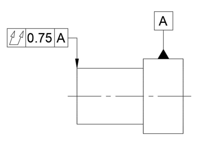
Total Runout Feature Control Frame
The feature control frame (FCF) of total runout describes how it applies to the specified feature. It uses a standard layout and symbols to convey the tolerance type, tolerance limit, specific conditions and reference points to give complete information about the applied total runout callout.
The leader arrow of the FCF points to the surface under control or its extension line.
The FCF for total runout is a fairly straightforward one. As with all other GD&T callouts, it consists of three blocks.
- Geometric characteristic block
- Feature tolerance block
- Datum block
Geometric characteristic block
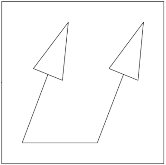
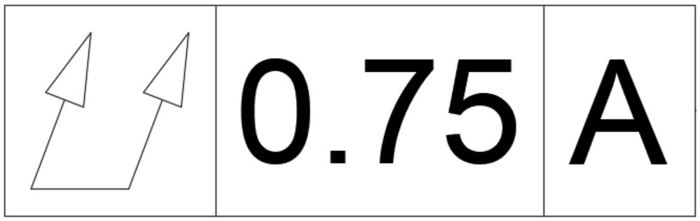
This block gives information about what callout is applied by housing the total runout symbol. You may already know that the symbol for (circular) runout is an arrow pointing northeast.
Since total runout measures the runout across the entire length, the runout symbol is made of two arrows pointing northeast with their tails connected by a horizontal line.
The arrows signify that total runout measures circular runout from one end of the specified part surface to the other, with the horizontal line representing the surface under control.
Feature tolerance block
This block gives information about how the callout applies to the surface. It gives information about the type of tolerance zone, tolerance limit, and material condition modifiers, if any.
The tolerance zone is not diametral, hence there is no diameter symbol in this block. The block contains the tolerance limit for the surface under control.
For a cylindrical surface, this stated limit represents the radial separation between the concentric cylinders that make up the tolerance zone. For a flat surface, the limit represents the difference between the two virtual planes of the total wide tolerance zone.
In all cases, total runout controls a surface without a material condition modifier. It is always applied RFS (Regardless of Feature Size) which is the default mode for all geometric tolerances.
Datum block
Total runout requires a datum in the FCF to derive the runout tolerance zone for the callout. It may use a datum axis or a datum surface, depending on the type of control needed.
Choosing the right datum is important as it will dictate how well it rotates in service. For most applications, it will be the axis of the shaft with the bearing surface that will be used as the datum.
Another fairly common feature seen with total (as well as circular) runout is that of a multiple datum or a compound datum feature. A callout can reference multiple datums to define part requirements better and each of them can be used for as many FCFs as needed.
The datums are placed one after the other, each in a separate box, and are known as primary datum, secondary datum and so on. Multiple datums usually find use in shafts with multiple diameters.
Compound datums are when more than one datum is placed in the same box, separated by a dash. They are two datums but they work as one. When measuring in such a case, the part is held along both axes, but together, they form a single axis.
How to Measure Total Runout
Metrology offers several ways of measuring total runout. Inspectors may use a CMM or manual method.
Using a CMM offers greater accuracy but requires a skilled operative. The manual method is easier and cheaper to implement.
Let us see the step-by-step process to measure total runout using the manual method.
Setting up the apparatus
The apparatus to measure total runout includes two large precision V-blocks, a small V-block, a straight edge (a flat, straight piece of metal), a dial or height gauge, and the part under observation.
The precision V-blocks are connected securely to the surface plate or any other smooth surface (usually a highly ground granite block) for stability. The inspector then places the cylindrical part’s (rotor, shaft, etc.) surface with the datum axis on the V-blocks.
The next step is to align the dial gauge to obtain a linear, smooth and continuous motion along the entire part surface. We start on this with a straightedge for accuracy.
The straightedge is held flush against the precision V-blocks. Inspectors sometimes use petroleum jelly to ensure smooth relative motion between the straightedge and the V-blocks. The small V-block is inverted, and the inspector connects the dial gauge to this V-block.
The dial gauge with a V-block is now held against the straightedge and adjusted in a manner such that the tip of the dial gauge connects with the part surface.
The idea is that precision V-blocks line up against the datum axis of the part, and the dial gauge lines up with the datum axis through the straightedge.
Measurement
The inspector now butts up the dial gauge along the cylindrical part at one of its ends. It is important to ensure that there is no gap between the straightedge and the V-blocks. One must also make sure that there is a small pressure on the dial gauge tip to measure variation in both directions.
Calibrate the dial gauge to zero, spin the part on the V-block and make a note of the maximum reading. Now start moving the dial gauge in a straight line along the part surface without spinning it.
Whenever a movement is observed on the dial gauge, wait and spin the part and record the maximum value. Continue this motion until the dial gauge reaches the other end of the part.
Final results
The inspector now compares the variations on the dial gauge at the different positions along the part length. The highest variation obtained is the Total Runout tolerance for the part. If this variation is within the specified tolerance limit in the FCF, the inspector approves the part.
Uses of Total Runout
The use of total runout is not as common as other circular callouts, as it places very tight restrictions on part geometry. Total runout mainly finds application in high-speed rotating parts with high surface contact area. A low total runout effectively prevents vibration, oscillation, and noise in the entire part when it rotates at such speeds.
Some parts where total runout is used are as follows.
- Large pump shafts
- Motor rotors
- Complex gears
- Drills
- Transmission shafts
- Axles
- Conveyor rollers
- Bearing journals
Important points to remember
- Total runout applies to the entire surface simultaneously. It puts tight restrictions on a part and is therefore used sparingly.
- The leader arrow points to the surface or its extension line.
- It cannot be called without a datum.
- The total runout tolerance zone is the spacing between two concentric cylinders or between two flat planes, depending on the feature under total runout control.
- Total runout is always applied RFS and never with MMC/LMC (no modifiers).
- Due attention must be given to any other geometric tolerances that may be indirectly controlling the size, shape, orientation or location of the feature under total runout control.
