


The fourteen types of geometric tolerances in GD&T are divided into 5 main types of control. These are form, location, orientation, profile, and runout.
Form controls determine the shape of individual features in a part. They consist of the following four types of geometric tolerances – straightness, flatness, circularity and cylindricity.
In this post, we shall learn about the flatness callout and how to use it in the right place for maximum efficiency.
What is Flatness?
Many applications need parts with a flat surface. No surface is perfectly flat but using GD&T, we can develop parts with a surface that is flat enough for our application.
The flatness callout controls the uniformity of a surface or a median plane as needed. It defines two parallel planes on either side of the flat surface as the tolerance zone for the surface. All the points on the specified surface must lie between these two planes for part approval.
As flatness refines a surface, we can also use it in a tolerance stack without interfering with other requirements.
Flatness vs Other Characteristics
It may seem like flatness is very similar to other geometric as well as regular tolerances in terms of the final result. So let’s do some 1:1 comparisons in order to make sure the difference is clear to everybody reading this article.
Flatness vs straightness
Flatness is the 3D equivalent of the surface straightness control. While straightness has parallel lines representing its tolerance zone, the flatness tolerance zone is formed by two parallel planes.
Thus, while straightness only makes sure that a single line on a surface has to be within the limits, GD&T flatness does the same for a collection of lines – a surface.
Flatness vs parallelism
These two are often confused. Parallelism is not a standalone callout. It needs another feature such as an axis or a surface to relate to. It cannot function without a datum.
On the other hand, flatness does not need a datum. We can use flatness on a surface that is not parallel to any other surface, so there is no reference point to compare the result with other than the closed system itself.
Flatness vs surface finish
This probably causes the most confusion out of these comparisons.
While both control surface variations, the surface finish does it on a much finer scale. The measurement for the surface finish is shown as an average while for flatness, the difference between the maximum height and depth is shown as the worst case.
Flatness vs regular tolerancing
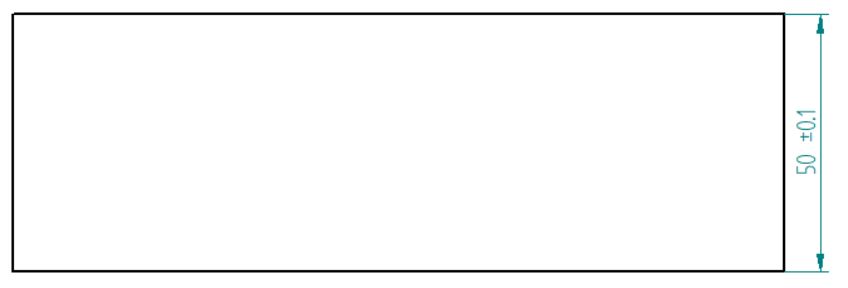
The image above has a tolerance of +/- 0.1 mm for thickness. All in all, this gives exactly the same result in terms of flatness – it guarantees it as does the one below.
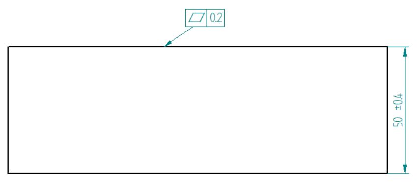
But this one has both the flatness callout AND a +/- tolerance for part thickness. As you can see, the flatness is still inside the same limits – 0.2 mm in total. But now the thickness of the part can vary up to 0.4 mm in both ways or 0.8 mm in total.
Thus, flatness can be achieved without restricting any other dimensions, making it easier to obtain and lowering the total cost.
- Personal account manager
- Quality assurance
- Payment terms for companies
- On-time delivery by Fractory
How to Show Flatness on a Drawing?
We show flatness tolerance on a drawing through a feature control frame. The feature control frame of flatness is quite straightforward.

The first block contains the geometric characteristic symbol for flatness. It is represented by a parallelogram.
Since the tolerance zone for flatness is a total wide zone, there is no need for a symbol in the second block for the tolerance type as this is the default zone. The second block, therefore, contains only the tolerance value and the material modifiers as needed.
Similar to other form controls, the flatness callout does not need a datum for reference. The leader arrow points to the surface that is under control.
At times, the leader arrow may point towards a size dimension. This indicates that the derived median plane is under flatness control.
What is Flatness at Maximum Material Condition?
Flatness with an MMC modifier can be a bit confusing since flatness is a form control. Form controls do not work with material condition modifiers. So is this callout even valid?
The validity of this callout depends on the type of feature it is applied to. If we call it for single planar surfaces, then this will not be a valid callout.
Flatness with an MMC modifier is a valid callout only when we apply it to a Feature of Size. When the callout is applied for a FOS such as width, instead of controlling the flatness of the surface, it controls the derived median plane. This callout is found in ASME Y14.5-2009, para 5.4.2.1.
Designers use this callout when a certain local size (width, for instance) needs a control tighter than the overall form.
As Rule no. 1 states, a size tolerance controls form as well. The tolerance zone of the size tolerance restricts the controlled feature within the stated measurements. This requirement is no longer in effect though, when we use the flatness callout with MMC as the geometric tolerance adds to the size tolerance (this condition overrides rule no. 1).
In other words, the flatness callout now controls the form and the size tolerance controls only the local width.
Measuring the Tolerance
There are different ways to check if the final measurements conform to the tolerance set by flatness. The method depends on the surface, so we are going to discuss each instance separately.
Single planar surfaces
Flatness measurements require a surface plate and a height gauge, probe, or a surface of some type. We cannot measure it by simply placing the part on a surface plate or a slab and using a height gauge as this would mean we are measuring parallelism with reference to the bottom surface.
Using a height gauge

ARVE error: url: https://www.googleapis.com/youtube/v3/videos?part=snippet%2Cstatistics&id=WwUqPiQ9JAQ&key=AIzaSyAQ7WFzTAUrOX-FjsIrFS3JwZBFzgIvloc Status code 200 expected but was 403.
To measure flatness with a height gauge, we need to hold the reference feature parallel. Advanced CMMs (Coordinate measuring machines) can inspect flatness very well. They create virtual planes that mimic the surface to be inspected. This gives accurate measurements.
The height gauge is then run over the entire surface in such a way that it covers every area. We add the maximum positive and negative measurements on the height gauge to calculate the total variance. This variance must be less than the flatness tolerance value to approve the part.
Using a surface plate
Machinists sometimes use a surface plate to inspect flatness. The part is held face down on the surface plate and a height gauge is brought in contact with the specified surface through a hole in the surface plate.
Then, the height gauge and the parts are moved in a manner that covers the full length and width of the surface and the flatness variance of the actual surface is calculated.
Feature of size (Flatness at MMC)
When we are measuring flatness at MMC, we are in fact measuring the flatness of the derived median plane. To inspect flatness when applied to a feature of size, we have two methods:
Using a functional gauge
In this method, we hold two height gauges at opposite ends of the feature of size. Consider a flat plate and the FOS under control through the flatness callout is the width.
We hold a height gauge on the top and the bottom surface in line with each other. The height gauges measure the local thickness. We move them all over the surface to ensure that the entire surface is within the size tolerance.
The second method is to use a gauge that has a cavity that can fit the plate at the virtual condition boundary. Virtual condition boundary is the total available tolerance limit when we add the geometric tolerance and MMC. For approval, the plate must fit in this gauge.
Using a CMM

ARVE error: url: https://www.googleapis.com/youtube/v3/videos?part=snippet%2Cstatistics&id=QVjhQn6q5Lw&key=AIzaSyAQ7WFzTAUrOX-FjsIrFS3JwZBFzgIvloc Status code 200 expected but was 403.
A CMM is capable of making many different types of measurements. But measuring this callout requires some additional preparations.
Consider the same plate as before with the same FOS under control. The plate would have to be positioned in a manner such that the probe can reach both surfaces. Then we mark points on the surface and measure the local thickness at these points. If these thicknesses are within the size limits, we start calculating the midpoint of these opposing points and join them together. The derived median plane then starts to take shape.
We arrive at the flatness tolerance by subtracting the maximum local thickness of the plate. Now, if the derived median plane’s flatness variance is less than the allowable flatness tolerance, the part is within specification.
Benefits of Using Flatness Tolerance
Engineering tolerances come in many different shapes and forms (literally), each with its own nuances. Hence, they have different applications and benefits. Flatness is no exception.
Flatness controls the waviness or variation in the surface without putting tighter constraints on the surface.
We use flatness in parts where good mating of two surfaces is crucial but the orientation isn’t that important. Sometimes, designers use the flatness callout to give the entire surface an equal amount of wear. This prevents any wobble when the parts mate.
One of the most common use cases is applying flatness to sheet metal parts. Laser cutting is one of the most widely used thermal cutting processes. Depending on various factors, the sheet may get deformed during the cutting operation.
Specifying the flatness levels with GD&T will help to ensure that the sheet conforms to your application’s requirements, whether it ends up as a tabletop or a side sheet for a conveyor.
All in all, it is a simple-to-use tolerance that can help in a lot of cases to avoid any setbacks in the latter stages (assembly phase) of a project.
