

The geometric dimensioning and tolerancing (GD&T) standards in ASME Y14.5-2018 define five main types of controls for various part features. These are form, location, orientation, profile and runout. The form control in GD&T controls the form of individual part features.
Circularity belongs to the form control group. It controls the geometry of circular features such as cones, cylinders and spheres.
In this article, we shall learn about the circularity callout and how we can use it to ensure the final part’s maximum closeness to its intended design.
What is Circularity?
The geometrical tolerance of circularity is one of the four types of form control, the others being straightness, flatness and cylindricity. Also known as roundness, it control’s a feature’s circular nature such as the diameter of a cylindrical pin or a hole.
The aim is to set a limit to the desired accuracy of the circular feature in relation to a perfect circle.
Circularity Tolerance Zone
The circularity callout defines a two-dimensional tolerance zone for the actual part surface. The tolerance zone consists of two concentric circles that lie on a plane that is perpendicular to the central axis of the part feature.

The difference between the radii of these two circles defines the permissible tolerance limit for the feature.
To understand it better, one may imagine an infinite number of tolerance zones in contact with one another to cover the entire surface (like discs in a stack). All the zones may not be of the same size (as in the case of a cone).
For part approval, all the points on a circular feature’s cross-section must lie in their respective tolerance zone, i.e. between the two circles. Thus, a sequence of circular tolerances can be used to determine the conformity to requirements of various cross-sections.
Circularity vs Other Callouts
Circularity may sometimes be confused with other callouts. Each callout has a specific function and a method of measurement.
A designer chooses the right callout for an application after considering various factors such as the degree of accuracy, tolerance limit, and ease of measurement. The following information will help us understand the difference between the different radial callouts in geometric dimensioning and tolerancing, and in making wiser choices regarding the same.
Circularity vs cylindricity
Cylindricity is the 3D counterpart of circularity. While the latter concerns itself with only the roundness of the feature, the former also controls the straightness of the circular feature’s central axis.
Cylindricity tries to bring the feature’s form as close as possible to a perfect cylinder.
Designers use cylindricity when, in addition to the diametral tolerance, the feature’s straightness plays an important role in the part assembly. For instance, a pin may have the diametral variation well within limits, but if it isn’t straight enough, it will not fit the hole.
Cylindricity is also different from circularity in that it is meant for features with a constant diameter, thus not suitable for conical shapes, for example.
- Personal account manager
- Quality assurance
- Payment terms for companies
- On-time delivery by Fractory
Circularity vs coaxiality
The coaxiality callout keeps the difference between the central axes of a part’s multiple circular features within limits.
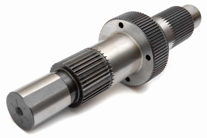
A part may consist of multiple circular features, like in the image above, situated at various positions along its length. Even if all the features are perfect circles, there will be wobble should the axes not align sufficiently.
In order to prevent wobbling, the central axis of all features must coincide. This is especially important for high-speed applications. Coaxiality keeps this variation under control.
Circularity is applied to a single feature, whereas coaxiality needs multiple features. Another key difference is that circularity does not need a datum whereas coaxiality cannot function without a datum axis.
Circularity vs concentricity
Concentricity is a special case of coaxiality where multiple features exist on the same plane.
When a plane perpendicular to the part axis contains diameters of multiple features (for example, inner and outer diameter of a hollow pipe), the concentricity callout ensures their centres are close enough to prevent wobbling.
Circularity vs runout
Runout (or circular runout) combines circularity and concentricity to control the complete form of the feature. The tolerance zone for runout is similar to a circularity zone, hence it is also a 2D measurement.
Runout captures the errors in circularity and concentricity into a single measurement. It is the sum total of circularity and concentricity errors.
In case a part is perfectly concentric, runout measurements give the circularity error. Similarly, when a part has perfect roundness, runout represents the error in concentricity.
Unlike circularity, runout also needs a datum axis.
Circularity Feature Control Frame
We use a feature control frame to apply the circularity control to a surface. It specifies all the important information for the callout in a standard manner for easy understanding by everyone who interacts with the concerned part’s drawing.
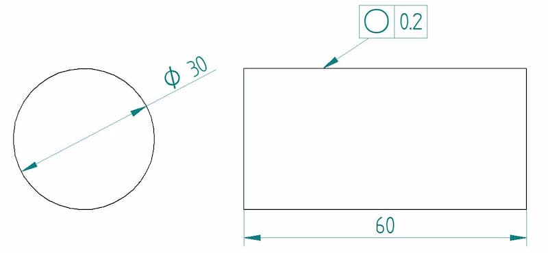
The feature control frame for circularity is quite easy to implement. As with other GD&T callouts, we will explain circularity’s feature control frame using the three general compartments as follows:
- Geometric characteristic block
- Feature tolerance block
- Datum block
Geometric characteristic block
This block contains the symbol for the circularity callout. Circularity is represented by a circle in this block.
Feature tolerance block
This block specifies the tolerance limit applied to the surface for the callout. Material condition modifiers are not applicable to circularity, hence they are not present in this block. Thus, it only contains the numerical value of the tolerance limit.
Datum block
The circularity callout does not need a datum because we apply it to individual features. The callout controls only the form of the surface and has nothing to do with the cross-section’s position on the part.
Measuring Circularity
There are many methods to measure circularity. All these methods require some skill and can be difficult to perform in the beginning. The means for measuring circularity are as follows:
- Using a height gauge
- Using a CMM
- Using a micrometre
Using a height gauge
Circularity can be measured using a turntable and a height gauge. To measure circularity, we carry out the following steps:
- Fix the part in a turntable (or a vee block) and constrain it so that it rotates along the central axis.
- Select a cross-section and set a height gauge probe at this cross-section. When selecting the height gauge, the inspector must ensure that the range of the height gauge (or dial gauge) is greater than the tolerance limit for the part.
- Ensure the height gauge is touching the part and calibrate it to zero.
- Rotate the part and log down the readings for a complete rotation.
- Plot the recorded values onto a polar graph or feed them into a computer program to create graphs that easily convey the part’s form. Check whether the part tolerance is within limits by ensuring that the total variation on the gauge is less than the specified tolerance limit.
- Repeat the same procedure at other cross-sections to obtain a complete picture of the part’s circularity.

ARVE error: url: https://www.googleapis.com/youtube/v3/videos?part=snippet%2Cstatistics&id=wNHaObwYlAk&key=AIzaSyAQ7WFzTAUrOX-FjsIrFS3JwZBFzgIvloc Status code 200 expected but was 403.
This type of setup may sometimes be referred to as a roundness measuring instrument. It contains a turntable and an adjustable stylus that can measure many other characteristics as well.
Besides circularity, it can measure straightness, perpendicularity, coaxiality, cylindricity, circular runout, total runout and parallelism.
Using a CMM
An alternate method of inspecting circularity includes the use of a coordinate measuring machine (CMM). The machine’s stylus takes measurements at four (or more) points of a particular cross-section. The variation is calculated by using the least-squares method.
The machine repeats the procedure at multiple cross-sections to ensure the entire part meets the roundness specification.
Roundness measurements recorded through this method are the most accurate.
Using a micrometre
A micrometre can also measure the circularity of a part, especially if it is the outer form (as in a pin). It is measured as a two-point measurement at various points of the same cross-section.
After recording these measurements, the minimum value obtained is subtracted from the maximum value and halved to get the roundness measurement.
The accuracy of the measurement improves with the increase in the number of measurements at a cross-section. An amazing feature of this method is that the only equipment needed is a micrometre, hence it is easy to perform with simple tools available at hand.
Note on measurement
Circularity inspection in the case of spheres is difficult to measure as any cross-section passing through the centre of the sphere is subject to tolerance limits. Thus, unlike cylinders and cones, measurements need to be taken in multiple planes to satisfactorily inspect a part.
Most machined parts do not have an oval shape and are usually made of a number of lobes. Circularity inspections can give the wrong measurements when the part is made of an odd number of lobes.
When we use a two-point measurement method (e.g. a micrometre) on a part that has an odd number of lobes that are evenly distributed, the results will show that the part is perfectly round when it’s not.
This error can lead to the approval of parts that need further machining. This is how circularity measurements can be tricky and, therefore, need skilled inspectors.
Uses of Circularity
Circularity is an extremely common callout that is used quite frequently in the manufacture of many different products. It controls the circular shape in circular, cylindrical, conical and spherical features.
It is used in parts such as bearings, shafts, pins, spools, pipes, etc. Circularity ensures that these parts function without any wobble and wear out evenly. This is especially important in high-speed applications.
Thus, circularity is often a part of many engineering drawings.
Points to Remember
- The tolerance zone for circularity is a radial tolerance zone, not a diametral one.
- The control works only when applied to a round feature.
- At each cross-section, the callout applies independently of other cross-sections.
- Circularity measurements can give the wrong measurements in some scenarios.
- No material condition modifiers (LMC /MMC) are part of the feature control frame.
- The circularity tolerance limit must be less than that of any other callout that also controls the circularity of that feature.
