

In mechanical engineering, tolerances set the allowable deviation from assigned dimensions. The use of tolerances helps to ensure that the final product is readily usable, especially if it is a part of a larger assembly.
Not setting a tolerance in a critical area may render the part unusable according to the design intent, as each fabrication method comes with a certain level of inaccuracy.
However, pinpointing a suitable tolerance makes sure that the manufacturing company knows to tackle a few specific points in the production process with more attention. This can be the difference between perfectly mating parts and scrap metal.
What Is Tolerance in Engineering?
Engineering tolerance is the permissible variation in measurements deriving from the base measurement.
Tolerances can apply to many different units. For example, the working conditions may have tolerances for temperature (° C), humidity (g/m3), etc. In mechanical engineering, we are mainly talking about tolerances that apply to linear, angular and other physical dimensions.
But regardless of the unit, a tolerance states an acceptable measurement range from the base point (nominal value).
Let’s say you are designing a sieve to separate 3.5 mm pebbles from 2.5 mm pebbles. You want the smaller pebbles to fall through the holes while keeping the larger ones on the sift.
The larger pieces of rocks vary in size between 3.3 mm and 3.7 mm. The smaller ones are in the range of 2.3…2.7 mm.
To ensure that only the smaller ones, all of them, will actually fall through the holes while keeping the larger ones on the sift, you can set the nominal value for the hole diameter as 2.8 mm. At the same time, manufacturing accuracy will mean that you may end up with some holes at 2.6 mm.
Adding a lower limit of -0 mm and an upper limit of +0.3 mm guarantees that all the holes will be between 2.8 and 3.1 mm in diameter.
Dimension Tolerances
As machines can not perform to perfection, the final dimensions of a product will definitely vary from the stated measurements. For example, a 15 mm hole on a drawing may end up 15.1 mm for laser cut parts.
So let’s see what you can do to make sure that the deviations are in the direction you would prefer them in. For this example, we are going to use linear dimensions.
Nominal Value
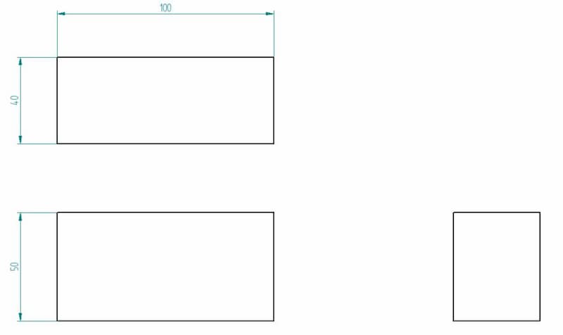
The nominal value is the basic dimension you usually give on a drawing. Without specifying the allowed tolerances, manufacturers will try to stay close to the value but there will be some sort of deviation as machine capabilities, setup, machinist competence, etc. all play a role.
Lower Deviation
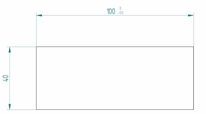
Adding a lower deviation tells the manufacturer how much smaller a certain measurement can be. This is noted using the “-” sign.
When making the part on the drawing, a measurement between 99.5 and 100 mm is acceptable. Anything under or above is not within the set limits.
Upper Deviation
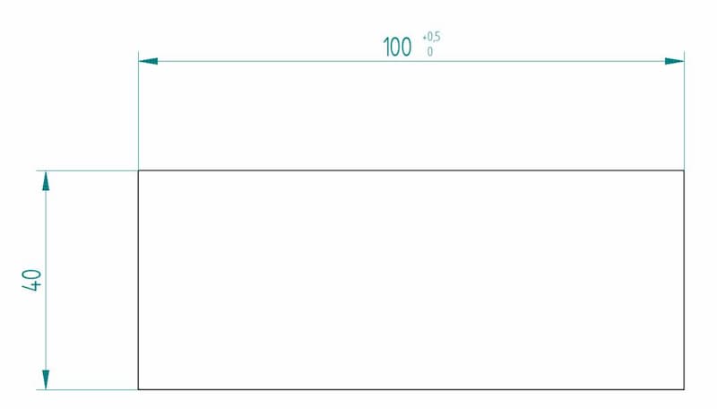
Upper deviation is the exact opposite of lower deviation. Adding it shows how much larger a measurement can be compared to the nominal value.
So the final measurement can be anywhere between 100 and 100.5 mm according to the tolerance limits on the drawing.
Bilateral deviation
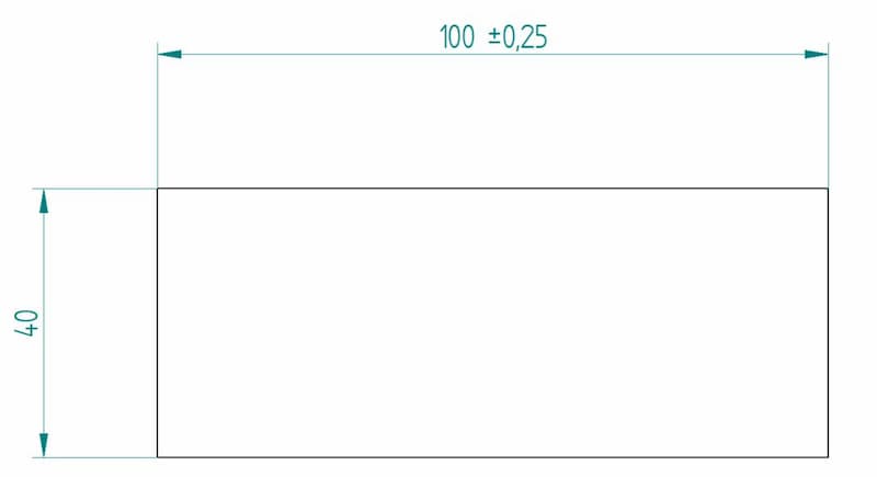
A third way to give a tolerance range is by using bilateral deviations.
The drawing states that 99.75 is the minimum acceptable dimension and 100.25 mm is the maximum. Thus, the total “room for error” is still the same – 0.5 mm – but it can go either way from the nominal value by 0.25 mm.
A founded question here might be – is there any difference between a nominal value of 99.5 mm and an upper limit of +0.5 mm and a nominal value of 100 mm and a lower limit of -0.5 mm?
Now, if the manufacturer has made a box full of parts that fit into the range of 99.5 to 100 mm, they can send the parts out in both cases. So at this stage, there is essentially no difference.
However, the production partner will take the nominal value as the main reference point to strive for during the manufacturing phase. Thus, the 99.5 +0.5 mm box will likely contain more parts with a measurement of 99.6 mm and the 100 -0.5 mm box will come back with a larger portion of parts having a measurement of 99.9 mm.
- Personal account manager
- Quality assurance
- Payment terms for companies
- On-time delivery by Fractory
General Tolerances
An engineering drawing may include general tolerances in the form of a table or just a little note somewhere on the drawing (e.g. “ISO 2768-m”).
They can be applied to several conditions, including linear dimensions, angular dimensions, external radius, chamfer heights, etc. In Europe, the standard to follow is ISO 2768. ASME’s Y14.5 is the US version of a similar standard but does not cover general tolerances.
So, what does a note like ISO2768-m mean on a drawing?
That requires the manufacturer to follow the m (medium) tolerance class when making the parts. This applies to all dimensions unless stated otherwise on the drawing. Thus, a specific tolerance for a hole overrides the general tolerance requirements.
Let’s include the linear dimension table for a better explanation:
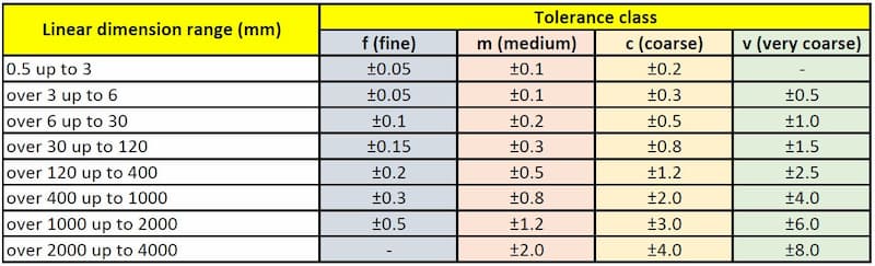
Here you can see that if a linear dimension falls into the 6 to 30 mm range, the permissible deviation is +/- 0.2 mm when looking at the m (medium) column. And for a dimension between 400 to 1000 mm, a tolerance of +/- 0.8 mm is allowed.
So 25.2 mm is acceptable for a 25 mm cut and so is 599.2 mm according to the standard for a 600 mm nominal value.
Fits
Shaft and hole matings come with a lot of different options and always require tolerances to obtain the right fit. But what is a fit in short?
Limits and fits describe the allowance between the shaft and the hole. Allowance, in turn, is the maximum dimensional difference between the diameters of the two.
There are three types of shaft-hole engineering fits.
Clearance Fit
This type of fit requires a shaft diameter to be smaller than that of the hole. Meaning that there will always be a gap between the two.
If the engineering solution needs the two to be able to slide or rotate independently of each other, this is the way to go.
So, in this case, both the shaft and the hole have tolerances that will ensure no overlapping.
Transition Fit
This option means that the maximum shaft size is bigger than the minimum size of the hole. At the same time, the minimum shaft size is also smaller than the maximum size of the hole.
So it is neither a clearance fit nor an interference one. Depending on the final measurements, the tolerances allow for both scenarios to happen while not going into extremes.
Interference Fit
Here, the shaft diameter size is always bigger than the hole. Even when the shaft is at its minimum diameter and the hole at its largest.
An interference fit ensures there is no movement between the two parts. Application of force is necessary during the physical fitting. Heating the hole, freezing the shaft and using a lubricant can all help to ease the process.
GD&T
Geometric dimensioning and tolerancing adds another side to engineering tolerance basics.
The system may seem a little daunting and intricate at first but helps to convey requirements in a universally standardised way. GD&T defines the geometric tolerances for engineering products using in-part references.
For example, you can use it for defining the parallelism of two surfaces.
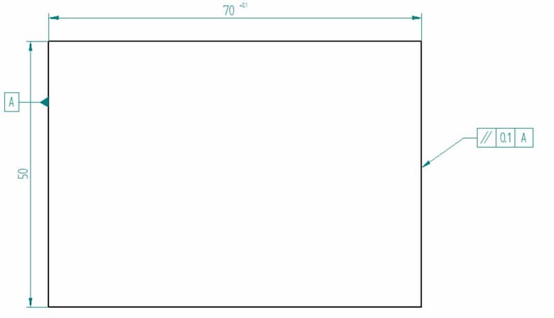
On the left, you can see the datum feature symbol. This assigns the left-hand surface as a reference.
The feature control frame pointing to the right side of the block has three elements – the parallelism symbol, the tolerance (distance between two parallel planes) and the datum reference.
So, what can we make of it all?
The left surface acts as a reference plane. As the machines will not be able to make both sides perfectly parallel but we require a certain limit, we gave it a parallelism tolerance.
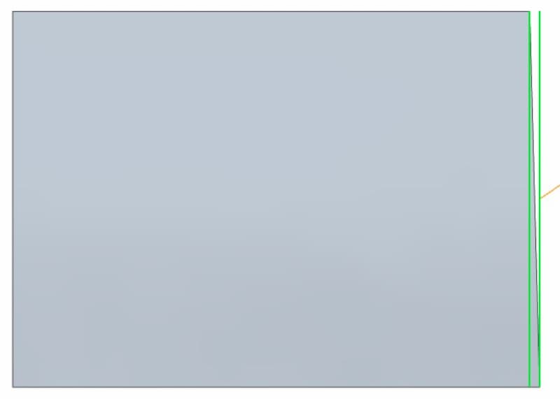
Thus, the right side has to be parallel to the left side within a 0.1 mm tolerance, allowing for some deviation. The image above shows a possible outcome.
The right side is clearly tapered but within the limits (the green planes), therefore satisfying the set parallelism requirements.
Why Tolerance Matters & Where to Use It?
As already said, a tolerance range sets the manufacturer a boundary for deviation. If your engineering project requires a certain level of precision, there is no better way of guaranteeing it than using the tolerance system.
If you do not include them on your drawings, the manufacturer will use their in-house standard. This may be a class of general dimensions or something fully custom.
Everything measurable, from linear dimensions to weight and material hardness will always vary from part to part. When the design does not take the variation into account, components may not fit together or give too much slack, resulting in early failure.
So should you now slap on tolerances for everything, defining each pin with a maximum material condition tolerance and each hole with a minimum material condition tolerance?
No, definitely not.
First, you have to take the manufacturing method into account. It matters whether you are looking to use laser cutting or plasma cutting. The more precise the fabrication method, the more accurate tolerance you can ask for.
Secondly, precision costs. Higher demands mean that you need to pay more. So pinpoint the exact requirements only as necessary and include them in your order. Do not slap on just any tolerance here and there, or you won’t be able to compete with the market as your product prices will be wildly over the top.
If you are using our manufacturing platform to get instant quotes for STP models, just include a PDF drawing with all the necessary tolerances. We can still read all the other dimensions straight from the model, so keep the drawing simple and only mark down the info regarding dimensions that need to stay within certain limits.
