

When selecting a material for a particular application, it is important to consider the service conditions it will be subjected to. Choosing the material with the right properties ensures a long-lasting lifetime.
A property that is considered more than any other is the ultimate tensile strength of the material. This strength refers to the maximum load that the material will be able to withstand before failure takes place. The factor of safety is then selected to further reduce the risk of breakdown.
However, in many applications, the load is not constant. The load’s magnitude and direction may vary in a regular or irregular manner. Such loads are known as fluctuating loads and can result in a breakdown that can happen at load values far below the ultimate tensile strength.
In this article, we shall learn about the phenomenon of material fatigue and how we can avoid failure caused by it.
What is Fatigue?
Fatigue can be explained as the weakening of a material due to the application of fluctuating loads that result in damage to the material’s structure and eventual failure. The damage starts locally and builds up over time and can end in a catastrophe.
There are many fluctuating loads that parts are subjected to during service. A few examples are as follows:
- A point on the wheel of a railway coach as it comes into contact with the railway track. On coming in contact, this point on the wheel is subjected to a compressive load by the metal track. When it moves away from the bottom, the compressive force on that point subsides. This happens once every rotation and will happen millions of times in a single journey.
- Traffic passing over a bridge applies a fluctuating load on the bridge. The bridge is subjected to the highest sagging load when the traffic is closest to the middle of the bridge. This force is removed when there is no traffic.
- The hull of a boat when it passes over waves is subjected to constant tensile and compressive forces as it makes way. This is especially pronounced during rough weather as the vessel pitches.
Understanding Fatigue Failure
Fatigue failure is something everyone has encountered while trying to break a metal wire.
The process includes bending the wire back and forth numerous times. Each back-and-forth bending is one cycle. When the wire finally breaks, you can count the number of cycles it took to lead to the initial crack and final break.
Knowing the number of cycles and the loading stresses gives the fatigue strength of that material.
If you tried to break the wire just by pulling from both ends, the force requirements would have been pretty high. At the same time, bending only requires minuscule forces and arrives at the same result.
The wire was subjected to fluctuating loads at the bending point as the top and bottom part of the wire cross-section were alternately stretched and compressed. With enough number of load cycles, the wire breaks.
This is an example of fatigue failure. Thus, it can happen quite easily even at small loads and a small number of load cycles, depending on the material.
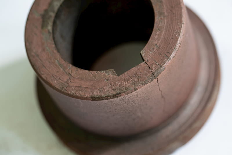
It is also worth mentioning that fatigue failure does not happen gradually. It is instantaneous, like a brittle material just breaking into smaller pieces.

ARVE error: url: https://www.googleapis.com/youtube/v3/videos?part=snippet%2Cstatistics&id=hASl6d3z3BM&key=AIzaSyAQ7WFzTAUrOX-FjsIrFS3JwZBFzgIvloc Status code 200 expected but was 403.
It is also far less predictable than regular failure as there are few prior indications. These indications are difficult to perceive with the naked eye. In regular failure, due to excessive loading, necking will be observed but there is no necking before fatigue breakdown occurs. This makes it impossible to predict exactly at what point in time a part will fail due to fatigue.
To prevent such a situation, the parts must be closely inspected and changed after a recommended number of load cycles. The number of cycles depends upon the material characteristics and the magnitude of the load. A higher load means a shorter lifecycle. This can be better understood using an S-N curve which we will get to shortly.
Failure Process
Fatigue failure happens without warning but on careful observation, some indications are evident.
Formation of the initial microcrack
On continuous exposure of the material to cyclic loading, minuscule cracks start to develop at high-stress points. These cracks can be observed by non-destructive testing methods.

ARVE error: url: https://www.googleapis.com/youtube/v3/videos?part=snippet%2Cstatistics&id=xEK-c1pkTUI&key=AIzaSyAQ7WFzTAUrOX-FjsIrFS3JwZBFzgIvloc Status code 200 expected but was 403.
Dye penetrant testing for inspection of diesel generator engine connecting rods during routine overhauls is one such example of crack detection. If cracks are found, the part is replaced with a new or reconditioned spare part.
Crack propagation
Once a fatigue crack has occurred, it propagates through the part with every load cycle. While spreading through the material, it will usually produce striations on the surface.
Striations are marks on the surface that show the position of the crack tip. These striations are a tell-tale of the development of a fatigue crack. The crack propagation is extremely slow when the crack is first initiated and is referred to as Stage I crack growth.
Fracture
When the crack reaches a critical size and the stress intensity at the point exceeds the fracture toughness of the material, the crack spreads at a high speed.
This type of fast propagation is known as Stage II crack growth and it happens in a direction perpendicular to the applied force.
Over time, the material is unable to handle any further loading and complete fracture occurs. This failure is immediate and can result in serious consequences for the workers using the machine and the machinery itself.
- Personal account manager
- Quality assurance
- Payment terms for companies
- On-time delivery by Fractory
Machine Components Prone to Fatigue
Some parts of a machine are more likely to succumb to breaking due to fluctuating stresses. One must be aware of such parts so that a breakdown can be avoided.
Shafts
Fatigue is on the top of the list when looking at shaft failure causes. Crankshafts, for instance, have to face serious cyclic loading. They form an integral part of many prime movers such as diesel generators, marine engines, vehicle engines, and reciprocating compressors.
Substandard design is the primary cause of damaged shafts. A crankshaft fillet rolling process may be used to improve its fatigue life.
Other shafts such as those in reciprocating and centrifugal pumps, motors, etc. are also subjected to cyclic loads resulting in a danger of breakdown.
The stress comes from different points of load. For example, at one end of the shaft is the motor which rests some of its weight on the shaft. There may be 2 bearings acting as points of support. At the same time, the rotational speed needs transmitting, maybe in the form of a sprocket-wheel and chain, both of which load the shaft further.
During rotation, the direction of the load is constantly changing subjective to the axis of the shaft. Thus, a break can occur similarly to our previous example of a wire.
Bolts
Bolts are known as a source of possible failure. They have to resist the tensile and compressive stresses due to machinery movement/vibration.
Insufficient bolt tightness gives room for more movement. Thus, the bolts must be tightened to a load exceeding the maximum working load.
Gears
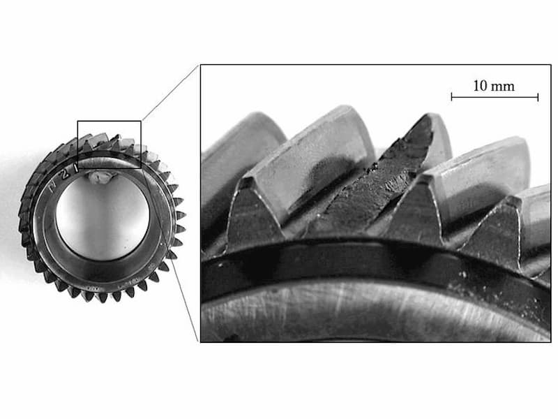
Gears transmit power through their teeth. These teeth deal with high loads when they are in contact with the other mating gear’s tooth. When they move away from this position, the stresses are removed. Cyclic loading occurs as the magnitude of forces on a tooth changes continuously.
Furthermore, the load is not evenly distributed on the entire length of the teeth. This localisation of load can further exacerbate fatigue issues.
Fatigue Strength
Fatigue strength is the ability of a material to resist fatigue failure.
ASTM defines it as the limiting value of stress (denoted by SNf) at which failure occurs after Nf number of load cycles. This number of cycles can be from a few cycles up to a large number depending upon the load and material.
After a certain number of load cycles have passed, the material can fail at any point and it is prudent to change it as soon as possible.
Fatigue Limit
Fatigue limit, denoted by Sf, is defined as the value of stress at which Nf (number of cycles at which failure occurs) becomes very large. Nf can be increased by reducing the stress value of the cyclic load.
When keeping the load below the fatigue limit, a part can withstand a huge number of cycles, usually more than 10 million but up to 500 million.
The difference between fatigue strength and fatigue limit is in the number of cycles. It is considerably higher with fatigue limit. Therefore, engineers try to design their parts so that they are kept under the fatigue limit during work.
Calculating the Fatigue Limit
There are various fatigue tests available that allow us to determine the fatigue limit of different materials. These are as follows:
- The stress-life method. In this method, the fatigue life of materials is calculated by subjecting it to different stress amplitudes. Then the curve is plotted. This curve is also known as the S-N curve.
- The strain-life method. When the strain produced due to cyclic loading is no longer elastic, it can be used instead of stress to plot a graph of strain vs. life.
- The crack growth method. In this method, the amount of crack growth per stress cycle is calculated. This gives us the rate of crack growth an helps us estimate the number of cycles required to reach critical size for a crack.
- Probabilistic methods. This is based on stress/strain-life or crack growth methods and improves the accuracy of predicted service life. The above methods do not account for probability distribution by themselves. However, we know that not all parts will fail at the same time once Nf stress cycles have passed. Using probability distribution helps us narrow down the number of cycles without failure.
Endurance Limit
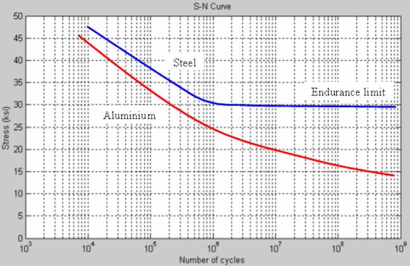
It is evident from the graph that the S-N curve becomes progressively flatter as the stress values are reduced. This is the case for most materials.
There comes a point where the curve for steel becomes horizontal. This means that below this stress value, the material will never fail because of fatigue. This stress limit is known as the endurance limit.
At the same time, aluminium does not have such properties and while it can last more cycles with a lower load, there is no endurance limit.
The difference between fatigue limit and endurance limit is that the endurance limit does not define a limited number of cycles after which the breakdown will occur. The part basically has infinite life and will not exhibit fatigue failure. It has an indefinite fatigue life.
S-N Curve

ARVE error: url: https://www.googleapis.com/youtube/v3/videos?part=snippet%2Cstatistics&id=o-6V_JoRX1g&key=AIzaSyAQ7WFzTAUrOX-FjsIrFS3JwZBFzgIvloc Status code 200 expected but was 403.
Fatigue life prediction can be done by plotting the S-N curve, where S stands for Stress applied and N stands for the number of load cycles. Most S-N curves are plotted in laboratories where different specimens are tested at varying stress values using a metal coupon testing machine. The specimen’s Nf is noted. Nf is the number of cycles at which failure occurs.
Then these points are plotted on a logarithmic S-N curve to accommodate large values of Nf. Linear regression is then used to form a continuous curve instead of discrete test data points on the graph.
The finished curve resembles a hyperbola to some extent. The equation for the curve is a derivative of SN=constant.
This means that with decreasing stress amplitude, number of stress cycles increases exponentially. A single equation cannot be used for the entire curve and different equations are defined for data points within a selected range. These equations can be calculated manually or through software like Solidworks.
Once an S-N curve is available, it can be used to determine the fatigue life of a part if the cyclic load value is known.
Accounting for Fatigue in Design
Owing to excellent research on the metal fatigue phenomenon in the last few decades, a lot of information is available to design parts more efficiently.
When designed within the endurance limit, the material will practically last forever provided corrosion and other factors are not present. Let’s take a look at how proper design can improve the life expectancy of materials.
1. Designed within the endurance limit. The maximum cyclic load that will be applied during service must be within the endurance limit to prevent fatigue failure.
2. Fault-tolerant design. The design must account for the failure of parts. As far as possible, it must be ensured that a single part’s failure does not cause a complete stoppage of the system or irreparable damage to the machinery.
3. Regular renewal of vulnerable parts. The design must take into account the fatigue limits of various parts and must include recommended service duration for these parts. These service periods can then be added to the preventive maintenance system for easy review and part renewal.
4. Damage tolerance. While designing a part, the likelihood of the existence of defects in a new part must be accounted for. It must be assumed that cracks may already be present.
5. Risk assessment. The risk of part failure must be regularly assessed to ensure it remains within acceptable levels.
Other than design, testing and repair must be carried out to prevent fatigue failure.
