

Power transmission is a process required in almost every piece of machinery. From the tiny motors in pop-up selfie cameras to the innovative transmission lines of the Large Hadron Collider, power transmission applications are all around us. We use power transmission methods to transmit power from the prime mover to the driven machinery for its function.
There are four main types of power transmission – mechanical, electric, hydraulic and pneumatic. In this article, we shall learn about mechanical power transmission, its types and the pros and cons of each type.
What Is Mechanical Power Transmission?
Mechanical power transmission refers to the transfer of mechanical energy (physical motion) from one component to another in machines. Most machines need some form of mechanical power transmission. Common examples include electric shavers, water pumps, turbines and automobiles.
In most cases, the rotational movement of the prime mover is converted into the rotational movement of the driven machinery. However, the speed, torque and direction may change.
Occasionally, they may convert rotational motion into translational motion (back and forth movement) depending on the application’s functional requirements. Such change may be carried out using linkages or other machine elements.
Types of Mechanical Power Transmission
Different machine elements can transmit power between shafts in machinery. The most common mechanical power transmission methods in use in the engineering industry today are:
- Shaft couplings
- Chain drives
- Gear drives
- Belt drives
- Power screws (lead screws)
Shaft couplings
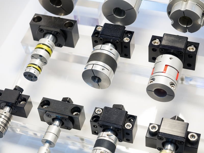 Shaft couplings connect two shafts and transmit torque between them. The shafts may be in line, intersecting but not parallel, or non-intersecting and non-parallel. To cater to the needs of various applications and environments, many different types and sizes of couplings are produced.
Broadly, there are two types of shaft couplings- rigid and flexible. Rigid couplings do not permit relative motion between shafts, whereas flexible couplings do. Hence, flexible couplings can handle some shaft misalignment.
Some couplings, such as the split muff couplings, can be fixed onto shafts without moving them. In contrast, most others require shaft movement for installation/removal.
Advantages
- Shaft couplings are low-maintenance machine elements
- They can absorb shock and vibration
- They can handle radial and axial misalignment
- They provide heat isolation
- Maintenance-free and permanently lubricated designs are available
Disadvantages
- Shaft couplings cannot be used for non-intersecting parallel shafts
- Rigid couplings may damage the shaft if misalignment creeps in
- Backlash may develop over the service life, putting the couplings, bearings and drive components under additional stress
- Some couplings may loosen over time, damaging the drive components
- Personal account manager
- Quality assurance
- Payment terms for companies
- On-time delivery by Fractory
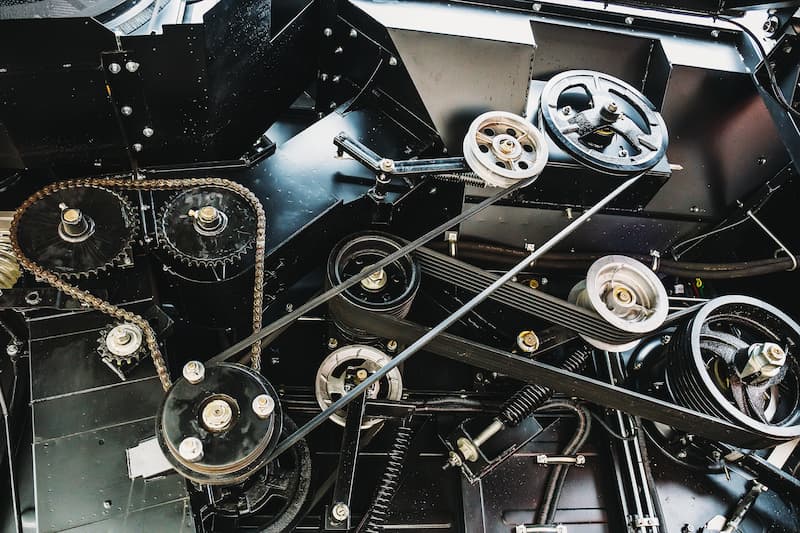
Belt drives
Belt drives are a fairly common sight in industrial applications. A belt drive system consists of two pulleys and a belt (or rope). The belt firmly grips both pulleys and transfers power from the driving shaft to the driven shaft through friction. The belt drive works equally well for slow and very high speeds and thus finds use in high-speed applications such as air compressors.
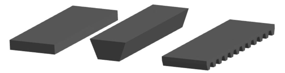
Just like other drives, there are many belt drive designs that are great for specific applications. Belts can power multiple parallel pulleys and change the speed as needed. They can also absorb shock loads to a certain extent, protecting other drive parts. Both pulleys rotate in the same direction unless it is a cross-belt drive. There are three main types of belts in belt drives – flat belts, V belts and toothed belts.

ARVE error: url: https://www.googleapis.com/youtube/v3/videos?part=snippet%2Cstatistics&id=vvH_yjy7Ezc&key=AIzaSyAQ7WFzTAUrOX-FjsIrFS3JwZBFzgIvloc Status code 200 expected but was 403.
Flat belts are great for general-purpose applications with low to medium torque demands. Typical applications include grinders, separators, roller conveyors, fans, water turbines, etc. Flat belts are reversible and can transfer power from both sides. There is no wedging effect in flat belts. This makes the energy losses negligible, and the mechanical efficiency can be over 98%. It can handle dust and dirt reasonably well and thus, has a longer service life compared to other alternatives.
V belts are better for medium to high torque demands. A V belt has grooves on the inside surface that fit into wedges on the pulleys. The driving shaft pulls the belt by the grooves, which pulls the driven pulley on the other end. Such an operation causes wedging losses, which, in effect, decreases the efficiency of a V belt. V belts cannot handle dust and dirt as well as flat belts.
Toothed belt, also known as timing belt, has teeth on the inside surface of the belt that fit onto toothed pulleys or sprockets. This belt drive is used for high-power transmission and timing applications. Toothed belts are used in automobile and motorcycle engines to power and time camshafts.
Advantages
- Belt drives are more affordable than other drives due to low component cost and high efficiency
- They can transmit power over long distances
- Smoother and quieter operation compared to chain drives
- They can absorb shock and vibrations
- Belt drive provides some degree of overload protection through the slipping of the belt
- Lightweight and relatively durable
- Low maintenance costs
Disadvantages
- Belt slippage can vary the velocity ratio
- Short service life if not maintained well
- Finite speed range
- They apply a heavy load on the bearings and shafts
- To compensate for wear and stretching, they need an idler pulley or some adjustment of center distance
Chain drives
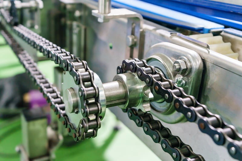 Chain drives are used to transmit power between two components that are at a greater distance. These drives consist of a roller chain and two or more sprockets. The driver sprocket’s teeth mesh with the roller chain and transfer torque to the driven sprocket. Chains can be commonly seen in power transmission in bicycles and motorcycles, but they are also quite common in industrial machines.
They can fit into tight spaces by using idler sprockets. Chain drives are also used in applications where timing is critical and any delay caused by slippage would result in problems. This is why they are used in marine diesel engines, as timing chains to transfer power from the crankshaft to the camshaft. The camshaft operates the exhaust valve and the fuel injection timing. If the timing is off, the engine will suffer.
Advantages
- A chain drive is more compact than a belt drive and can fit into relatively tight spaces
- It can transfer torque over long distances
- Contrary to belt drives, chain drives do not slip
- One chain drive can power multiple shafts at a time
- It has high mechanical efficiency thanks to little friction
- A chain drive can work in all kinds of service environments (dry, wet, abrasive, corrosive etc.) and at high temperatures
Disadvantages
- They are noisy and can also cause vibrations
- A chain drive cannot work with non-parallel shafts
- Some designs require constant lubrication
- Misalignment may cause the chain to slip off
- A chain drive usually needs an enclosure
- It requires an arrangement for chain tensioning in the form of a tightening idler sprocket
Gear drives
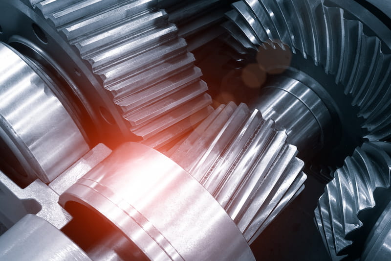 Gear drives use gears for motion and power transmission from one shaft to another. They consist of a driving gear (on the input shaft) and a driven gear (on the output shaft). Power transmission from the power source to the load takes place through the meshing of the gear teeth. Due to the many available designs, they can work in a number of orientations and applications.
A gear drive can handle higher loads compared to a chain drive but is only suitable for short distances, as the gears need to be in direct contact with each other. Using multiple gears in a gear train makes it possible to change the gear ratio, rotational speed, torque and direction as needed. Too many gears in a single system will, however, reduce mechanical efficiency.
Gear drives do not slip but they may develop some backlash over time. Backlash is the gap between two meshing gear teeth at the pitch circle. At lower outputs, it may only result in some minor calculation errors. But at higher power outputs, the backlash will send a shock through the entire gear train. On occasion, it can even cause damage to the gear teeth.
Advantages
- Suitable for high mechanical power transmission applications
- Gears are sturdy and have long service lives
- Compact setup
- Gears have high efficiency and do not slip
Disadvantages
- Not suitable when distances between shafts are high, a direct connection is needed
- Prone to vibration and noise
- Metal gears are heavy and increase the weight of the machine
- They do not offer any flexibility
- They require lubrication
- Shock loads can damage gears
- Costlier than other drives (chain, belt, etc.)
- Meshing gears require precise alignment
Power screws
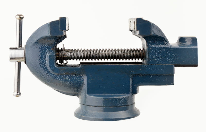
Power screws, also known as lead screws (leadscrews) or translational screws, are screws that either transmit or receive power. They are different from screw fasteners that are used to create temporary joints in machines. Power screw consists of a screw and nut that mesh with each other for power transmission.
In some cases, the nut is stationary while the screw moves for power transmission (screw jack and vice). In other cases, the nut is the power source and the screw is stationary (lathe lead screw).
Power screws are subject to considerable axial, horizontal and vertical forces in operation. They must have sufficient strength and bearing area to withstand them.
Lead screws can be seen in action in screw jacks, lathes, vices, mechanical presses, etc. They use the same principle as screw fasteners of converting rotational motion into linear motion to reduce the effort required to do work. The lower the pitch, the easier it is to lift, move or tighten objects with power screws. The most common thread profile for power screws is a square thread, followed by acme and buttress threads.
Advantages
- Power screws are cheap and reliable as they only have a few parts
- Some lead screws have self-locking property
- It requires little to no maintenance
- Capable of lifting heavy loads
- Smooth and quiet operation
- Low-pitch screws can give highly precise measurements, which are vital in machine tool applications (A micrometer works on the same principle)
Disadvantages
- High wear rate compared to other methods of mechanical power transmission
- Power screws have poor efficiency
- Not suitable for mechanical power transmissions with a very high torque demand
Choosing the Correct Power Transmission Method
Choosing the right power transmission method can be tricky. From the data above, it is clear that every type has its pros and cons. The differences may be very obvious in some areas, but subtle in others.
Sometimes, subcategories within a particular type will help improve performance in some aspects. But if engineers work backwards from their expectations from the drive, it will narrow down viable options and even help with the final selection.
In this section, we shall see five important power transmission factors that will help you select the correct method for your application:
- Angle between shafts
- Distance between the prime mover and the load
- Torque
- Temperature
- Maintenance concerns
Angle between shafts
Shafts can be parallel, intersecting, non-parallel but intersecting or non-parallel non-intersecting. Some mechanical power transmissions require that there is no relative motion between shafts (e.g. gear, chain & belt drives). In contrast, others can handle minor misalignment (e.g. flexible shaft couplings).
Distance between the prime mover and the load
The distance between the power source and load can further narrow down the choice. Where there is a considerable distance between shafts, a belt drive or a chain drive can be used. For short distances, shaft couplings and gear drives are more suitable.
Torque
For high torque applications, chain drives can be used as belt drives may slip. On the other hand, for low torque needs, flat belt drives and power screws are better.
Temperature
Materials such as rubber and synthetic compounds are not compatible with high-temperature environments. If such materials are used to manufacture belts in belt drives, they will start wearing out soon.
Alternatives such as chain and gear drives are better suited to high temperatures as they can quickly acclimatise to such environments and work efficiently. Such systems can also work with oil cooling methods. The same oil that is cooling the engine can be used to lubricate the drive. On the other hand, oil cooling is not possible with rubber as it will degrade the material.
Maintenance concerns
Maintenance issues such as tensioning, wear rate, alignment and lubrication can help an engineer determine the suitable mechanical power transmission method for the application.
Conclusion
Mechanical power transmission methods ensure that the load receives the power needed safely and efficiently. Different industries use different mechanical power transmission products and sometimes a combination of all to suit their respective needs.
At times, more than one method may be suitable for the same application. It will come down to comparing the pros and cons of each alternative to determine the most appropriate mechanical power transmission option for your design.
