

Mechanical engineering has become extremely complex with time. An average car today has about 30,000 machine elements when we count each one down to the smallest screw. These machine elements work in unison to run the car as intended by the machine design.
Some of these mechanical parts are elementary mechanical elements, whereas some others are in an assembly with other parts and perform a specific function in the car. The alternator, engine and carburettor are examples of such parts.
Learning about machine elements is the first step in creating efficient machines that solve pressing problems. They reduce human effort and surpass their capabilities significantly. In this post, we shall learn about machine elements and their types.
What Are Machine Elements?
In mechanical engineering, a machine element is the smallest mechanical part or part assembly in a machine. They usually perform a single function and cannot be replaced with multiple parts. For example, a bearing may be made of smaller parts such as balls, rings and seals, but it cannot perform its function if it were split up into its constituent mechanical parts.
Thus, a machine element may be defined as a part constituent (such as a fastener) or a distinct part (e.g. clutch) in machines. Broadly, machine elements can be divided into two main types.
- General-purpose machine elements
- Special purpose machine elements
General-purpose machine elements
These elements are the basic building blocks in many types of machines. Parts such as fasteners (screws, nuts and bolts, rivets, etc.), chains, shafts, keys, bearings and belts are examples of general-purpose machine elements. They usually perform the same function in all these machines.
In most cases, general-purpose machine elements come in sizes and shapes defined by international standards.
For example, hex bolts can be manufactured as per 18 different standards, the most popular being DIN 931 and DIN 933. In most of these standards, they are available in sizes from M3 to M48. This increases their usability in a variety of different machines, as replacements are easily available.
Special-purpose machine elements
These are mechanical elements that find specific use in machine design. Examples of such parts are the turbine in a jet engine, blades in a fan, pistons, crankshaft, etc. The mechanical design of these parts is customised as per requirements.
Let us consider the example of ship engines. They come in different designs, with the number of cylinders ranging from 6 to 14.
For each type of engine, the size of every component is redesigned. The exhaust valve, cylinder head, liner, piston, piston rings, connecting rod and crankshaft all come in different sizes for two different types of engines.
Types of Machine Elements
Both general and special purpose machine elements are elementary mechanical components that function together to make a machine work. Let’s see the various types of common machine elements and their uses.
Bearings
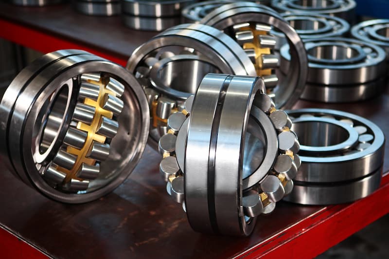
Bearings are one of the most common machine elements in machine design. Their job is to eliminate the friction between two moving parts. The mechanical design of rotating machines is incomplete without it. The primary purpose of bearings is to prevent direct metal-to-metal contact of the two parts and enable smooth relative motion between them.
They come in various shapes and sizes. The abundance of available bearing designs enables designers to select the most suitable bearing for different applications, ensuring maximum reliability, efficiency, performance and durability.
Bearings find use in a range of different motions, such as linear (conveyors), rotational (crankshafts), hinge (doors, windows) and spherical (ball and socket joint). They transmit radial loads, axial loads (thrust bearings), or a combination of both from the rotating element to the bearing housing.
Some applications of bearings are:
- Sliding doors/windows/drawers
- Engine crankshaft
- Conveyor pulleys and idlers
- Wind turbines
- Motors
Shafts

Shafts are long, cylindrical components used for the transfer of torque and mechanical power between two components. Designers use them when the distance between drive train components is too great for a direct connection, or if they operate in different environments.
For instance, in the case of a ship propeller, the distance is too great between the engine and the propeller warranting the use of a long shaft with multiple bearings along the way.
Similarly, the steam turbines powering the cargo oil pumps in oil tankers are isolated from the pumps by a bulkhead to eliminate the chances of ignition (different environments application). Only the shaft passes through the bulkhead from the engine room to the pump room.
The steam turbines in the engine room become extremely hot during operation. Even in the unlikely event of the atmosphere in the pump room becoming combustible (if cargo oil leaks), the mechanical design is such that the turbines will not act as sources of ignition.
A shaft may be solid or hollow, depending on the need. Solid ones are more compact, but their hollow counterparts have a greater load-carrying capacity for the same weight. For shafts under heavy loads during operation, designers prefer a hollow shaft as it has higher rigidity, stiffness and bending moments.
Some applications of shafts are:
- IC engine crankshafts/camshafts
- Vehicle axles
- Clocks and watches
- Motors
- Pumps
Keys
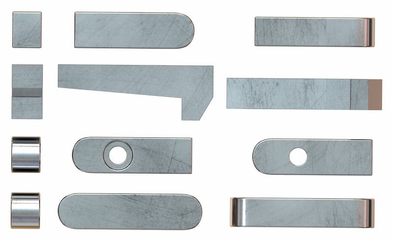
In machine design, keys are small mechanical components that connect shafts to rotating elements. In some cases, they may be solely responsible for the transfer of torque between the two elements.
Keys are placed between the shaft and the rotating element and have provisions cut out in both of them to fix the key in place. The cutout in the hub is known as the keyway. The bottom of the keyway where the key rests in the shaft is known as the keyseat. The complete assembly is known as a keyed joint.
A keyed joint permits no relative rotational motion but may allow axial motion to a small extent as keys are inserted in the axial direction. Due to such a function, keys must endure high compressive and shearing stresses. Thus, crushing failure and shearing failure are important considerations in a key’s mechanical design.
The various types of keys in machine design come in many standard shapes. The five main types of keys are round, saddle, spline, sunk and tangent.
Sunk key is the most common of them all. It comes in various sizes and shapes such as rectangle, square, parallel sunk, woodruff, gib-head and feather.
Some applications of keys are:
- Motors
- Marine propellers
- Gear drives
- Pulleys
- Sprockets
Couplings
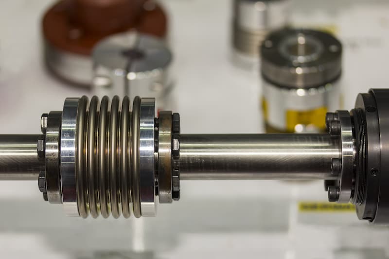
Couplings are mechanical components that connect two rotating in-line shafts, with the primary purpose of transmitting power in mechanical design. The entire assembly rotates at the same speed. A coupling may be rigid or flexible, depending on the need.
A flexible coupling can absorb any mounting errors as well as any minor misalignments between the shafts that may develop over time. They also absorb shocks and vibration, increasing the service life of the machines in the process. Unlike clutches, couplings do not engage and disengage.
These machine elements also isolate the heat transfer between the two ends in some applications. For instance, a motor can heat up considerably during operation. A coupling prevents this transfer of heat from the motor to the paired machine.
Some couplings work like fuses. If the torque exceeds a certain limit, they break and sever the connection between the driving and driven components to protect sensitive machinery. Such a coupling is known as Overload Safety Mechanical Coupling and is normally used for the protection of motors and drive systems in power transmissions.
Some applications of couplings are:
- Generators
- Motion control in robotics
- Automotive steering linkages
- Paddle steamers
- Car differentials
- Personal account manager
- Quality assurance
- Payment terms for companies
- On-time delivery by Fractory
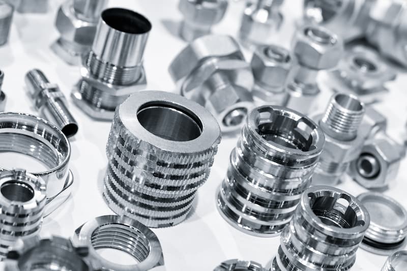
Fasteners
In mechanical engineering applications, different types of fasteners are used to hold together two or more machinery components. They create temporary joints which can be disassembled when needed. Some machines work under extreme conditions. The primary purpose of fasteners is to protect these machines against high pressures, excessive forces and vibration.
In machine design, it is important to be as specific as possible about the design or selection of fasteners in applications. This is to ensure that these machine elements can manage the forces that the product will be subjected to in service and the machines can function without failure. Fasteners are usually made from carbon steel, stainless steel, or alloy steel.
Some examples of fasteners are screws, nuts/bolts, split pins, rivets and circlips. And they are used everywhere, independent of the industry. The only question to ask is whether the assembly will need to be disassembled for maintenance or not, as in the choice of rivets vs bolts and nuts.
Gears
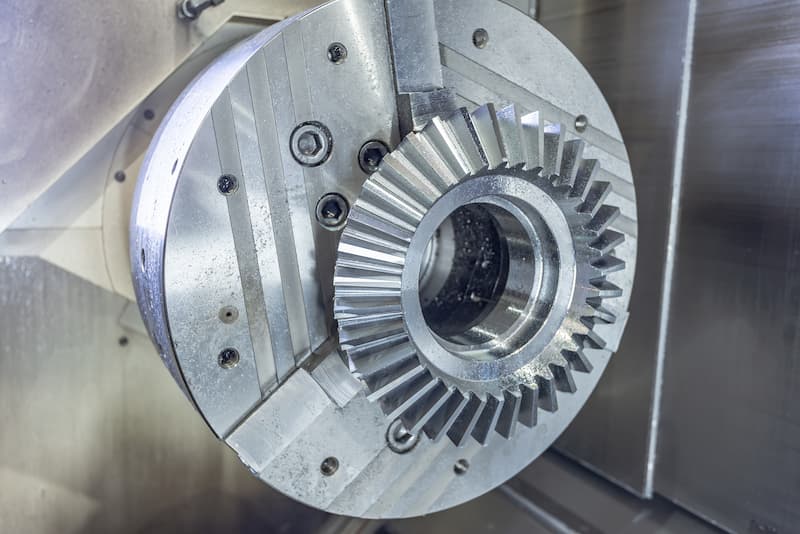
Gears are elementary machine elements with toothed wheels to transfer power and rotation between two shafts. They can increase or decrease angular velocity while simultaneously decreasing or increasing torque, following the laws of energy conservation. In essence, they act as levers in a translating mechanical system.
The teeth on two gears mesh with each other and transfer power from the driving shaft to the driven shaft. Usually, the shafts are parallel, but special gears are capable of transferring power between intersecting as well as non-parallel, non-intersecting shafts.
The capability to work efficiently in any orientation means they also come in a variety of shapes. Most gears are cylindrical in shape with teeth along the circumference. Others come in shapes that resemble a shaft (worm gear) or a rod (rack and pinion). Yet others have teeth on the face instead of the circumference (face gears).
While it is important to select the general gear type, due attention must also be paid to factors such as precision grade standard (DIN, AGMA, ISO), need for ground or heat-treated teeth, dimensions (face width, helix angle, module, number of teeth, etc.) and more.
Some applications of gears are:
- Clocks and watches
- Vehicle gearboxes
- Clocks and watches
- Mixers and blenders
- Washing machines and dryers
