

A shaft coupling is one of the most common machine elements because it is just so important in power transmission systems. Thus, they find use in a variety of applications and service environments.
As a result, designers and engineers have designed many variations of couplings for specific service conditions and environments over the years.
This article will familiarise you with the different types of couplings and discuss choosing the right option for your application.
What is a Coupling?
A coupling is a mechanical device that connects similar or dissimilar shafts in machines to transmit power and movement. It is usually a temporary connection (but can be permanent in some cases) and capable of removal for service or replacement. A coupling may be rigid or flexible.

ARVE error: url: https://www.googleapis.com/youtube/v3/videos?part=snippet%2Cstatistics&id=vHbQWFi7S9Y&key=AIzaSyAQ7WFzTAUrOX-FjsIrFS3JwZBFzgIvloc Status code 200 expected but was 403.
Due to the availability of many designs, there can be stark differences in the construction and function of two types of mechanical couplings. Some couplings can connect to shafts without moving the shaft, while most will require shaft movement for fitting.
In most cases, a coupling does not change the direction of motion or angular velocity, unlike gears. It cannot be connected or disconnected mid-operation, unlike clutches. Couplings can only transfer torque over short distances, for longer distances chain drives and belt drives are better alternatives. Couplings are often paired with lead screw assemblies to connect the screw shaft in-line to a motor.
The coupling works by maintaining a strong but flexible connection at all times between two shafts to transfer motion from one shaft to another. It does so at all values of loads and misalignment without permitting any relative motion between the two shafts.
The Purpose of Couplings
A shaft coupling can perform multiple functions in a machine. The design may incorporate more than one of these coupling features into the product’s function in advanced applications.
Let us take a brief look at what these are:
- Power transmission
- Shock and vibration absorption
- Misalignment accommodation
- Heat flow interruption
- Overload protection
Power transmission
The primary purpose in most cases is power and torque transmission from a driving shaft to a driven shaft — for example, a coupling connecting a motor to a pump or a compressor.
Absorb shock and vibration
A shaft coupling can smooth out any shocks or vibrations from the driving element to the driven element. This feature reduces the wear on the components and increases the service life of the setup.
Accommodate any misalignment
Misalignments between shafts can result from initial mounting errors or may develop over time due to other reasons. Most couplings can accommodate some degree of misalignment (axial, angular and parallel) between shafts.
Interrupt heat flow
A shaft coupling can also interrupt the flow of heat between the connected shafts. If the prime mover tends to heat up during operation, the machinery on the drive side is protected from being exposed to this heat.
Overload protection
Special couplings known as Overload Safety Mechanical Coupling are designed with the intention of overload protection. On sensing an overload condition, these torque-limiting couplings sever the connection between the two shafts. They either slip or disconnect to protect sensitive machines.
Types of Couplings
Couplings come in a host of different shapes and sizes. Some of them work great for generic applications, while some others are custom-designed for really specific scenarios.
To make an informed choice, it is important to be aware of the capabilities and differences between the different types of couplings. This section presents information about the following types of couplings and how they work:
- Rigid coupling
- Flexible coupling
- Sleeve or muff coupling
- Split muff coupling
- Flange coupling
- Gear coupling
- Universal joint (Hooke’s joint)
- Oldham coupling
- Diaphragm coupling
- Jaw coupling
- Beam coupling
- Fluid coupling
Rigid coupling
As the name suggests, a rigid coupling permits little to no relative movement between the shafts. Engineers prefer rigid couplings when precise alignment is necessary.
Any shaft coupling that can restrict any undesired shaft movement is known as a rigid coupling, and thus, it is an umbrella term that includes different specific couplings. Some examples of this type of shaft coupling are sleeve, compression and flange coupling.
Once a rigid coupling is used to connect two equipment shafts, they act as a single shaft. Rigid couplings find use in vertical applications, such as vertical pumps.
They are also used to transmit torque in high-torque applications such as large turbines. They cannot employ flexible couplings, and hence, more and more turbines now use rigid couplings between turbine cylinders. This arrangement ensures that the turbine shaft acts as a continuous rotor.
Flexible coupling
Any shaft coupling that can permit some degree of relative motion between the constituent shafts and provide vibration isolation is known as a flexible coupling. If shafts were aligned all the time perfectly and the machines did not move or vibrate during operation, there would be no need for a flexible coupling.
Unfortunately, this is not how machines operate in reality, and designers have to deal with all the above issues in machine design. For example, CNC machining lathes have high accuracy and speed requirements in order to perform high-speed processing operations. Flexible couplings can improve performance and accuracy by reducing the vibration and compensating for misalignment.
These couplings can reduce the amount of wear and tear on the machines by the flaws and dynamics that are a part of almost every system. As an added bonus they’re generally rather easy to install and have a long working life.
“Flexible coupling” is also an umbrella term and houses many specific couplings under its name. These couplings form the majority of the types of couplings in use today. Some popular examples of flexible couplings are gear coupling, universal joint and Oldham coupling.
- Personal account manager
- Quality assurance
- Payment terms for companies
- On-time delivery by Fractory
Sleeve or muff coupling
Sleeve coupling is the simplest example of a rigid style coupling. It consists of a cast-iron sleeve (hollow cylinder) or muff. It has an internal diameter equal to the external diameter of the shafts being connected. A gib head key is used to restrict the relative motion and prevent slippage between the shafts and the sleeves.
Some sleeve couplings and shafts have threaded holes that match up on assembly to prevent any axial movement of the shafts. The power transmission from one shaft to the other occurs through the sleeve, the keyway and the key. This shaft coupling is used for light to medium-duty torques.
The sleeve coupling has few moving parts, making it a sturdy choice as long as all the parts are designed keeping in mind the expected torque values.
Split muff coupling
For easier assembly, the sleeve in a sleeve coupling can be divided into two parts. By doing this, the technician no longer needs to move the connected shafts for assembly or disassembly of a coupling.
This is what a split muff coupling or a compression coupling is. The two halves of the sleeve are held in place using studs or bolts.
Similar to sleeve coupling, these couplings transmit power through the key. Split muff couplings are used in heavy-duty applications.
Flange coupling
In flange couplings, a flange is slipped onto each of the shafts to be connected. The flanges are secured to each other through studs or bolts and onto the shaft by a key. Using set screws or a tapered key ensures that the flange hub will not slip backwards and expose the shaft interfaces.
One of the flanges has a protruding ring on its face, while the other has an equivalent recess to accommodate it. This type of construction helps the flanges (and, in turn, shafts) maintain alignment without creating any undue stress on the shafts.
Flange coupling is used in medium to heavy-duty applications. They can create effective seals between two tubes, and hence, in addition to power transmission, they are used in pressurised fluid systems. Flange couplings are of three major types:
- Unprotected type flange coupling
- Protected type flange coupling
- Marine type flange coupling
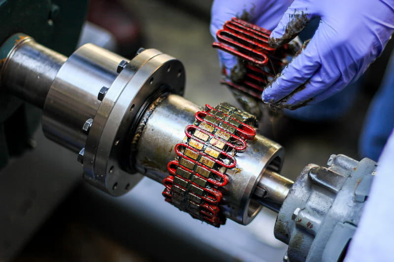
Gear coupling
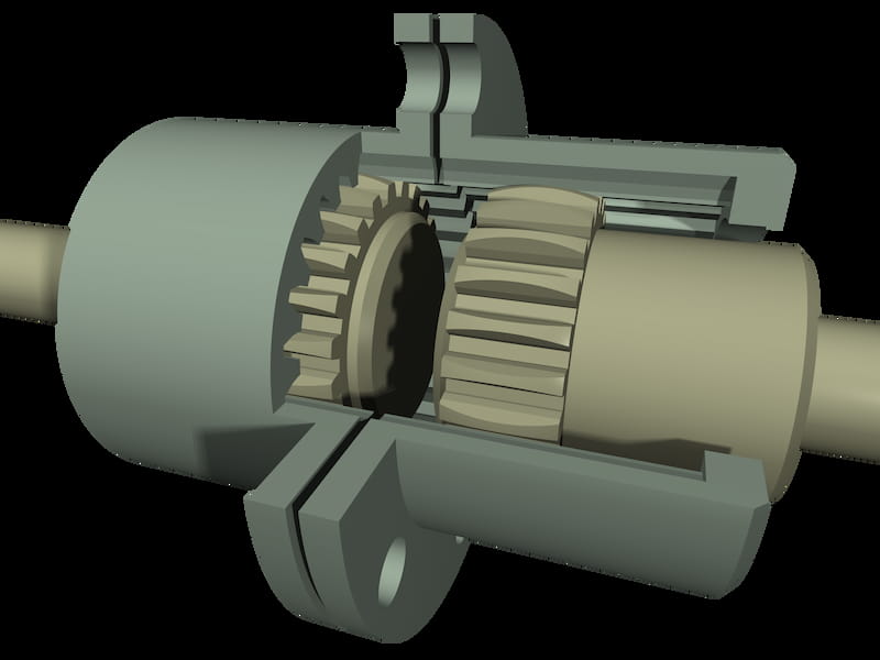
A gear coupling is very similar to a flange coupling. However, it is a flexible type of coupling and can be used for non-collinear shafts. Gear couplings accommodate angular misalignment of about 2 degrees and parallel misalignment of 0.25…0.5 mm.
The setup for gear couplings consists of two hubs (with external gear teeth), two flange sleeves (with internal gear teeth), seals (O-rings and a gasket) and the furnished fasteners.
The power transmission between the two ends of the coupling occurs through the internal and external gears in the gear coupling.
Gear couplings are capable of high torque transmission. As a result, they find use in heavy-duty applications. They require periodic lubrication (grease) for optimum performance.
Universal joint (Hooke’s joint)
When two shafts aren’t parallel and intersect at a small angle, we use a universal joint. This joint can accommodate small angular misalignment while providing high torque transmission capacity.
The universal joint consists of a pair of hinges connected through a cross-shaft. The two hinges are positioned at 90 degrees to each other. The cross-shaft maintains this orientation and is also responsible for the power transfer. The universal joint is not a constant velocity coupling, i.e., the driving and driven shafts rotate at different speeds.
They find use in a variety of different applications, hence the name. The most popular uses of universal joints are in car gearboxes and differentials.
Oldham coupling

ARVE error: url: https://www.googleapis.com/youtube/v3/videos?part=snippet%2Cstatistics&id=utEKKox2WHA&key=AIzaSyAQ7WFzTAUrOX-FjsIrFS3JwZBFzgIvloc Status code 200 expected but was 403.
Oldham coupling is a special shaft coupling used exclusively for lateral shaft misalignment. When two shafts are parallel but not collinear, an Oldham coupling is most suitable.
The design consists of two flanges that slip onto the shaft and a middle part known as the centre disc. The centre disc has a lug on each face. The two lugs are actually rectangular projections that are perpendicular to each other and fit into the grooves cut out into the flanges on each side.
The flanges are fixed to the shaft through keys. Thus, the power transmission takes place from the driving shaft to the key to the flange to the centre disc and then through the second flange to the driven shaft.
Oldham coupling is ideal for scenarios where there is a parallel offset between two shafts. Such parallel misalignment can happen in cases where power transmission is needed between shafts at different elevations. When the shafts are in motion, the centre disc goes back and forth and adjusts for the lateral variation.
Diaphragm coupling
Diaphragm couplings are great all-rounder shaft couplings. They can accommodate parallel misalignment as well as high angular and axial misalignment. They also have high torque capabilities and can transmit torque at high speeds without the need for lubrication.
Diaphragm couplings are available in various styles and sizes. The structure consists of two diaphragms with an intermediate member between them. The diaphragm is basically one or more flexible plates or metallic membranes that connect the drive flanges on the shafts to the intermediate member through bolts on both sides.
Diaphragm couplings were initially developed for helicopter drive shafts. But over the years, they have found much use in other rotating equipment as well. They are most commonly used in turbomachinery due to their high-speed function. Applications today include turbines, compressors, generators, aircraft, etc.
Jaw coupling
Jaw coupling is a material flexing coupling. It finds use in general low power transmission and motion control applications. It can accommodate any angular misalignment. Similar to diaphragm couplings, jaw couplings do not need lubrication.
This coupling consists of two hubs with intermeshing jaws that fit into an elastomeric spider. The spider is usually made of copper alloys, polyurethane, Hyrtel or NBR and is responsible for torque transmission.
Due to the elastic nature of the spider, it is suitable for the transmission of shock loads. It can also dampen reactionary forces and vibration pretty well.
Engineers use jaw couplings in applications such as compressors, blowers, mixers and pumps.
Beam coupling
A beam coupling is a machined coupling that offers high flexibility in terms of parallel, axial and angular misalignment. It is one of the best low-power transmission couplings.
A beam-style coupling has a cylindrical structure with helical cuts. The attributes of these cuts, such as their lead and the number of starts, can be modified to provide misalignment capabilities of varying degrees. In fact, engineers can make these changes without sacrificing the structure’s integrity as it is made of a single piece. Thus, a second name for beam coupling is helical coupling.
In essence, beam couplings are actually curved flexible beams. They are available in single-beam and multi-beam versions. Multi-beam couplings can handle greater parallel misalignment than single-beam couplings.
A beam coupling is more suitable for low-load applications as torsional windup can be a real issue. Thus, it is used in servo motors and motion control in robotics.
Fluid coupling
ARVE error: url: https://www.googleapis.com/youtube/v3/videos?part=snippet%2Cstatistics&id=11Q4g-oOLr8&key=AIzaSyAQ7WFzTAUrOX-FjsIrFS3JwZBFzgIvloc Status code 200 expected but was 403.
A fluid coupling is a special type that uses hydraulic fluid to transmit torque from one shaft to another.
The shaft coupling consists of an impeller connected to the driving shaft and a runner connected to the driven shaft. The whole setup is fixed in a housing, also known as a shell.
When the driving shaft rotates, the impeller accelerates the fluid, which then comes into contact with the runner blades. The fluid then transfers its mechanical energy to the runner and exits the blades at a low velocity.
A fluid coupling is used in automobile transmission, marine propulsion, locomotive and some industrial applications with constant cyclic loading.
Parameters for Choosing
Shaft couplings are an integral component of motion control and power transmission systems. They provide incredible advantages and combat many assembly and service environment issues when applied correctly.
To do this, designers must consider many factors to make the right choice. Being aware of them helps reduce instances of coupling failure and improve system capabilities. These factors are:
- Torque levels
- Alignment limits
- Rotational speeds
- Lubrication constraints
Torque levels
Most manufacturers use rated torque as a basis for classifying coupling. The value of torque depends on whether a coupling is used for motion control or power transmission applications. The former has lower torque and loads compared to the latter. Knowing the expected torque levels in an application will narrow down the selection of the right coupling.
Alignment limits
Different applications have different alignment needs. Similarly, some shaft couplings can only accommodate one type of misalignment, while others can handle multiple types.
Manufacturers also mention the misalignment limits for different types of misalignment for every coupling. This consideration helps further narrow down the search and pair the right coupling with the right machine.
Maximum rotational speed
Every coupling also has a maximum allowable RPM. This limit is also published with shaft couplings. General-purpose couplings cannot be used as-is for high RPM applications. High RPM couplings need static and dynamic balancing to ensure safe, smooth and noise-free service.
Such balanced designs are created by precise machining and appropriate fastener distribution. Using the expected RPM as a yardstick can help with the correct coupling selection.
Lubrication constraints
Sometimes, service conditions may prevent frequent relubrication of shaft couplings that need it. On the other hand, some shaft couplings are designed without the need for any lubrication over their entire life.
If the torque requirements are low, modified versions of conventional couplings are also available. These versions come with metal-on-metal lubrication or metal and plastic combinations to eliminate lubrication altogether. Designers must make the right coupling choice by evaluating the service conditions and application needs.
