

GD&T lists fourteen different geometrical tolerances according to ASME Y14.5-2009. These tolerances allow us to control and define part features in different ways. For ease of understanding, these fourteen tolerances have been segregated into five different groups based on similarities between them. These five groups are form, profile, orientation, location and runout.
In this article, we shall take a look at the profile of a line tolerance that belongs to the profile group along with profile of a surface. Line profile tolerance is quite common and it helps us to manufacture parts with complex shapes. But first, let’s start by defining what it is.
What Is Profile of a Line in GD&T?
The profile of a line tolerance is a 2D GD&T callout that can define and control a linear/curved feature or a surface cross-section within specified limits. We can use it to control the form, location, orientation and size of a feature. This callout can only be used on surfaces and cannot be used to locate a central axis or plane.
The line profile callout is typically used in the case of complex curves. These could be simple or advanced algebraic curves. The callout simply mimics the curve irrespective of the complexity.
Profile of a Line Tolerance Zone
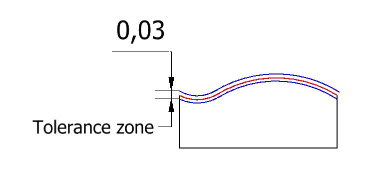 The line profile tolerance creates a true profile where the curve should ideally be located. The actual curve is evaluated with respect to this true contour. The actual curve must conform as much as possible to this true profile.
The tolerance zone is made of two parallel lines that follow the true profile in either direction. Unless stated otherwise, these parallel lines are assumed to be equidistant from the true profile.
The distance between the two parallel curves is the tolerance limit. Every point on the actual curve must lie between these two lines of the tolerance zone for approval.
Line Profile vs Other Callouts
ARVE error: url: https://www.googleapis.com/youtube/v3/videos?part=snippet%2Cstatistics&id=A5T11_0iMRk&key=AIzaSyAQ7WFzTAUrOX-FjsIrFS3JwZBFzgIvloc Status code 200 expected but was 403.
Profile of a line vs profile of a surface
The profile of a surface tolerance, is most closely associated with profile of a line. In fact, it is the 3D equivalent of the line profile tolerance. Profile of a line controls individual line elements on a single cross-section or any other linear feature, whereas surface profile controls the entire curved surface by taking the variance of adjacent cross-sections into account.
Profile of a line vs straightness/circularity tolerance
Straightness and circularity are great for controlling straight lines and circles respectively. They are easier to measure and control and this can be done with simple measurement instruments. In addition to both straight lines and circles, profile of a line can effectively control highly complex curves. This is not the case with straightness and circularity.
Besides, straightness and circularity tolerances can only control the form, whereas profile of a line can control the form, location, orientation and the size of a feature.
- Personal account manager
- Quality assurance
- Payment terms for companies
- On-time delivery by Fractory
Line Profile Feature Control Frame
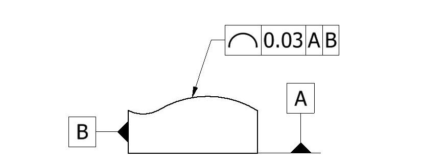
 The feature control frame (FCF) for any GD&T callout contains all the information required to correctly define how it applies to a feature or surface. It connects to the feature using an arrow known as the leader arrow. A typical FCF consists of three main blocks. These are:
-
Geometric tolerance block
-
Feature tolerance block
-
Datum block
Geometric tolerance block
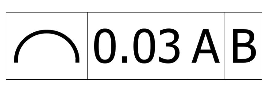
This block gives information about the type of geometric tolerance applied to a feature. The tolerance is represented by its symbol in the first block. The symbol for profile of a line is an inverted semicircle.
Feature tolerance block
This block gives information about how the geometric tolerance applies to a feature. It contains information about the shape of the tolerance zone, the tolerance limit and material modifiers, if any.
In the case of profile of a line, the tolerance zone is a 2- dimensional total wide tolerance zone. This zone is distributed bilaterally in relation to the true profile. This is the default zone and requires no special notation.
This is followed by the tolerance limit which specifies the width of the tolerance zone. The third symbol is for material modifiers but these do not apply when using profile of a line. This callout is only controlled by basic dimensions.
Datum block
This block represents datum elements that are used as references to locate/orient a part feature. Profile of a line tolerance may or may not be called out with a datum. In the absence of a datum, the line profile tolerance acts as a form control (such as straightness, circularity, flatness, etc) and is a refinement of a size tolerance.
With one or two datums, profile of a line controls the orientation besides the form. Location requires two to three datums. Whenever we use a datum, it is important to notify the distance using basic dimensions. Using basic dimensions, a profile control can also control the feature size.
How to Measure Profile of a Line
The means to measure the line profile will depend on the type of curve. The profile tolerance can very well be used as a replacement for different form controls in which case a simple setup consisting of a dial gauge and a surface plate would be sufficient.
When it comes to complex curves, more advanced and reliable instruments such as a CMM, VMM (vision measuring machine) or a 3D scanner are required. In each case, the actual surface must lie within the tolerance zone to prevent rejection. For complex curves, we trace the contour of a part using a probe, record multiple measurements and compare it to a virtual boundary through a CMM.
Uses for Profile of a Line Tolerance
A large number of parts in modern machines feature advanced curves and cross-sections that have to be manufactured accurately for functional reasons such as aerodynamics, ergonomics, etc. The profile of a line tolerance helps us achieve that. It can accurately define and communicate geometry requirements for parts with curved shapes. Some examples of parts where we use profile of a line are:
-
Turbine blades
-
Bearing housings
-
Car hoods
-
Airplane wings
