

GD&T consists of 14 geometrical tolerances that can be applied to any part feature to control them. These tolerances are described in detail in ASME Y14.5-2009.
Many of these 14 tolerances have features similar to each other in the way they control a part’s shape and dimensions, therefore it is important to understand what is the intended use of the part beforehand.
For ease of use, these 14 tolerances are divided into five main groups.
-
Form
-
Orientation
-
Location
-
Profile
-
Runout
In this article, we shall study the profile of a surface (or surface profile) callout that is part of the profile group mentioned above. These two callouts can help us manufacture geometries that have complex outer shapes with impressive details.
What Is the Profile of a Surface in GD&T?
The profile of a surface is an extremely powerful and versatile GD&T callout. It can be used on nearly all kinds of complex outer shapes where other tolerances are not easily applicable.
Some examples of surface profile use:
-
Aerospace: airplane wing, air intake for engine, turbine blades
-
Automotive sector: BiW, A-pillar, complex outer shape
-
Product design: design of complex outer shapes for consumer appliances such as coffee makers, smartphones and displays.

ARVE error: url: https://www.googleapis.com/youtube/v3/videos?part=snippet%2Cstatistics&id=61x3SdtXf8g&key=AIzaSyAQ7WFzTAUrOX-FjsIrFS3JwZBFzgIvloc Status code 200 expected but was 403.
Profile of a surface controls a part’s surface profile in accordance with the CAD model or the drawing. Many engineering parts such as turbine blades, car BiWs and airplane wings have highly complex surfaces. These surfaces need to be manufactured to great detail for functional reasons. The profile of a surface callout can help us manufacture these parts by controlling the surface profile during manufacturing and measuring results after production.
The profile of a surface generates a virtual surface that acts as the baseline to measure the actual surface. Thus, it is possible to create highly intricate surface profiles as long as they can be created as a CAD model. The required surface’s specification must also be within the capabilities of the fabrication process to be used.
Surface Profile Tolerance Zone
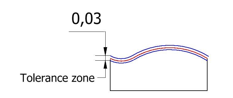
The surface profile tolerance zone consists of two parallel planes, bilaterally disposed on each side of the ideal curved surface (aka the true profile). Both planes follow the shape of the ideal surface and the distance between them is the tolerance limit for the callout. A smaller tolerance limit gives tighter control but may be difficult to manufacture. The points on the part’s entire surface must lie within the specified tolerance zone for it to be accepted.
Surface Profile Relation to Other GD&T Symbols
As mentioned above, the profile of a surface can effectively replace almost all of the GD&T Callouts whether they are curved or flat. Let’s see a few examples:
Profile of a surface vs form controls
When used without a datum, the profile of a surface can replace all the form controls.
The four form controls are
These form controls constrain the form of a part by creating a tolerance zone between two parallel surfaces. These planes can be either flat or cylindrical.
Profile of a surface vs orientation controls
When used with a datum callout, the profile of a surface can replace all the orientation controls.
The orientation controls are:
In order to orient a part feature in GD&T, we need a reference point such as a datum plane, line, or axis. By specifying a datum in the profile of a surface’s feature control frame, we can replicate the function of all orientation controls to maintain a surface in a particular position.
Profile of a surface vs line profile tolerance
The profile of a surface tolerance is the 3D equivalent of the line profile tolerance. While the profile of a line controls a specific cross-section on the part, the profile of a surface controls every cross-section across the entire length of the surface.
There are times when both profile controls may be applied together. In such a case the line profile’s tolerance is tighter than the profile of a surface. This is done to achieve greater control at critical cross-sections while the profile of a surface maintains a looser overall control over the full surface.
- Personal account manager
- Quality assurance
- Payment terms for companies
- On-time delivery by Fractory
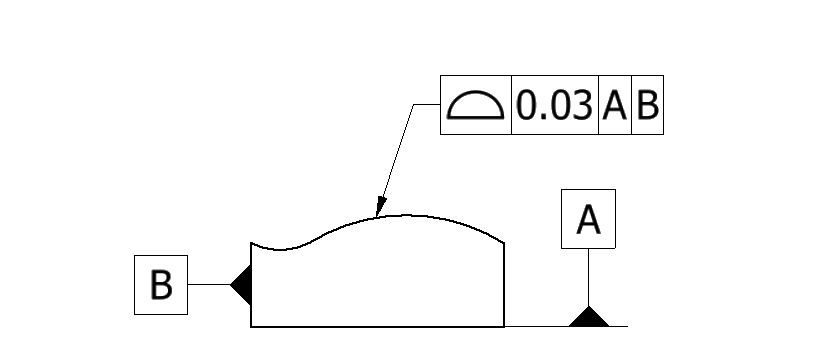
Profile of a Surface Feature Control Frame
A leader arrow connects the feature control frame (further referred to as FCF) of the profile of a surface tolerance to the part feature. Like any other FCFs in GD&T, the profile of a surface FCF can be divided into three distinct blocks. These are:
-
Geometrical tolerance block
-
Feature tolerance block
-
Datum block
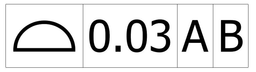
Geometrical tolerance block
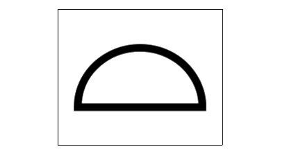
This block defines the geometrical tolerance applied to a feature by housing its symbol. The profile of a surface symbol is an inverted semicircle with a horizontal diameter connecting its two ends.
Feature tolerance block
This block contains specific information about how a tolerance applies to a feature. Since for the profile of a surface, the tolerance zone is a total wide tolerance zone which is the default zone, there is no special symbol for it. This is followed by the tolerance limit. This limit, also known as the tolerance value, is the distance between the two planes of the tolerance zone and is represented by its numerical value in the FCF.
This number is typically followed by material condition modifiers (MMC, LMC, etc.), but these do not apply to the profile of surface control.
Datum block
This is the third block in GD&T that houses the reference planes for the tolerances. In the case of a profile of surface control, the use of a datum is optional. When a datum is not present, the callout only controls the feature’s form. But if we want to control additional aspects such as the orientation, location, and size, we must define one or more datums as needed.
When to Use Profile of a Surface Tolerance?
As mentioned in the above examples, the profile of a surface can effectively replace almost all of the form and location tolerances. So the question then becomes:
Why isn’t it used everywhere?
The answer boils down to pricing. In order to measure the surface profile, the part has to be measured via a CMM machine. CMM machines can measure either with a probe or with a laser. Regardless both of these options are expensive because:
-
It takes time to program the machine and then measure. This is not feasible for parts in running production.
-
They require skilled operators: The operator should not just be trained in measurement, but he/she should also know how to interpret the drawings. Such operators don’t come cheap.
Hence it is strongly advised to engineers to make sure that the surface profile tolerance is necessary and no other GD&T can fulfil the requirement.
Important Points to Remember
Here are some best practices and important points to consider when using the profile of surface tolerance.
-
As with all GD&T, make sure that basic dimensions are used, when adding numerical dimensions for features controlled with surface profile control.
-
The numerical tolerance range for the surface profile depends on the following factor:
-
Is the intended surface exposed or assembled?
-
What kind of environmental factors will the part be subject to? Putting tight profile control on a bumper panel for example does not make sense if the part will expand and contract depending on the temperature
-
Therefore it is extremely important that tolerance chain analysis is conducted beforehand to find the numerical values that are put in the drawing.
Conclusion
The surface profile is an extremely powerful GD&T symbol that can be used for complex surface profiles for all kinds of parts. However, it should be used keeping in mind the associated costs for measuring and verification of parts.
