

As defined per ASME Y14.5-2009, GD&T uses 14 geometric tolerances for specific control over various part features. These controls enable the fabrication of many machine parts with enviable accuracy.
For ease of understanding, these 14 controls are divided into five main groups. These are form, profile, orientation, location and runout.
The tolerances under each of the five categories primarily control the feature of the category they belong to. For instance, the tolerances under the runout category (circular and total runout) control the part runout. But under certain circumstances, they may control other features as well.
Of the five groups, orientation tolerances control the tilt associated with part features. Angularity is a type of orientation control besides parallelism and perpendicularity.
In this article, we shall take a look at the angularity tolerance, its various aspects, feature control frame and measurement methods. Let us start by defining what angularity is.
What Is Angularity?
Angularity is a 3-D GD&T callout that helps maintain a specified angle between a feature (line or surface) and a reference feature. It can be used to reference a line with respect to another line but more commonly it is used to maintain a surface at an angle to a datum or reference plane. This is especially important for parts with angled surfaces that mate with other parts in an assembly.
At times, angularity finds use in aligning a feature of size, such as pins or holes in a surface, to the desired angle. In those cases, angularity controls the center axis of the hole to fix its orientation.
Angularity is also used to control the orientation of non-circular features such as tabs and slots. The angularity callout creates a tolerance zone around the mid-plane to control these features.
Angularity Tolerance Zone
The biggest misconception regarding angularity is that it creates an angular tolerance zone such as 30 degrees +/- 10′. This would mean that the feature is supposed to be at a 30 degrees angle in relation to a datum and is allowed an angular variation of 10 minutes on either side. But this is not the case with angularity.
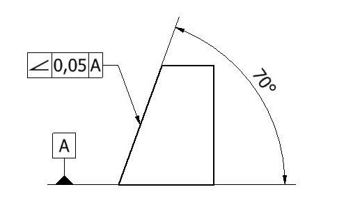
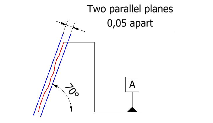
The shape of the tolerance zone changes with the feature being controlled. In the case of surfaces, the tolerance zone is expressed by two parallel planes that are aligned with the exact angle required by design. In other words, the zone is oriented to the datum at a basic (or theoretically exact) angle and the surface variation is allowed to float between the two planes.
If the zone width increases, the degree to which an erroneous angle is accepted also increases. Thus, it is the width of the zone that is indirectly restricting the permissible variation of the angle. For such a part to be in spec, all the points on the surface must lie within the envelope.
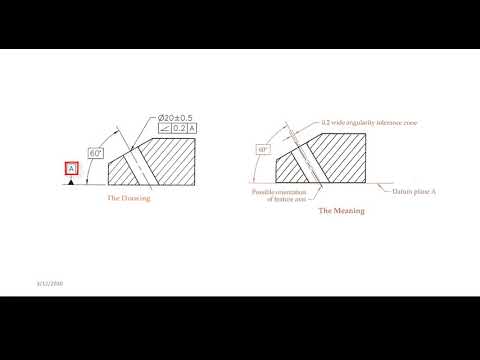
In the case of a circular feature of size, such as a cylindrical pin or a hole, the zone is expressed as a cylindrical tolerance zone around the axis of the said feature. This zone is aligned to the basic angle with respect to the datum and the diameter of the zone is specified in the feature control frame. Same as before, the zone’s diameter determines the permissible angular variation. As long as the center axis of the feature lies within the tolerance zone, the part is approved.
When used to control non-circular features of size, such as tabs and slots, angularity creates a planar tolerance zone with one plane on either side of the central plane. The center of the feature at each point must lie between the two planes of the tolerance zone.
ARVE error: url: https://www.googleapis.com/youtube/v3/videos?part=snippet%2Cstatistics&id=11MtQwunlvY&key=AIzaSyAQ7WFzTAUrOX-FjsIrFS3JwZBFzgIvloc Status code 200 expected but was 403.
Angularity vs Other Callouts
Angularity vs flatness
Angularity can be understood as oriented flatness. It uses the same concept and tolerance zone as flatness but is oriented at a specific angle to the datum. All the points on the part surface must lie between the two planes for both callouts.
The difference is that flatness is measured relative to itself and hence, works without a datum whereas the angularity tolerance references a datum. Thus, angularity controls the angle as well as the flatness of a surface.
If we only want to control the angle instead and not the flatness, we can use the tangent plane modifier (T in a circle) which controls the tangent plane to the surface instead of the entire surface thickness. This is especially important when working with natural materials as they have a certain thickness (plywood, wood, metal sheets) and defects such as wood knots.
Angularity vs perpendicularity and parallelism
Angularity bears similarity to perpendicularity and parallelism too. In fact, many books refer to perpendicularity and parallelism as special cases of angularity. They all require datum elements and create total wide tolerance zones to define the expected accuracy of a part. In this way, angularity is more similar to perpendicularity and parallelism than it is to flatness.
The only difference is that in the case of perpendicularity and parallelism, the angles are 90 degrees and 0 degrees respectively. Whereas for angularity, it can be any value from 0 to 90 degrees including both.
Thus, it is perfectly alright to apply angularity anywhere you would use perpendicularity or parallelism without any issues.
- Personal account manager
- Quality assurance
- Payment terms for companies
- On-time delivery by Fractory
Angularity Feature Control Frame
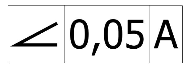
Angularity uses a simple and easy-to-understand feature control frame (FCF). The FCF marks the feature under control using a leader arrow that points to the feature or its extension line. The feature control frame can be divided into three distinct parts. Going from left to right, these three parts are:
-
Geometric tolerance block
-
Feature tolerance block
-
Datum block
Geometric tolerance block
This block in the FCF gives information about the type of geometric tolerance applied to the feature.
Each tolerance in GD&T has been assigned a specific symbol. The symbol denoting angularity is an acute angle opening to the right (⦟).
Feature tolerance block
This is the second block in the FCF and it explains the shape and magnitude of the tolerance zone for the callout. The first symbol in this block is for the shape of the zone.
As discussed earlier, there are two main types of tolerance zones in angularity. When applied to pins and holes, angularity creates a cylindrical tolerance zone which requires a diameter symbol to be placed in this block.
If the tolerance is a total wide tolerance zone as in the case of lines, surfaces and non-circular features, no extra symbols are needed as this is the default tolerance zone.
This symbol is followed by a numerical value known as the tolerance value. ASME defines it as the total amount a specific dimension is permitted to vary. It is the difference between the maximum and minimum limits.
For angularity, this is the width between the parallel planes of the planar tolerance zone or the zone diameter in the case of a cylindrical tolerance zone.
The next symbol is for material condition modifiers. When it comes to angularity, it is often called out with MMC in the case of pins and holes to ensure that little to no interference occurs between mating parts during assembly. This is represented by the letter M in a circle.
Datum block
This is the third and final block in the FCF. It gives information about the datum elements used as references for the angularity callout. The datum axis or the surface is represented by a letter on the drawing which is subsequently placed in the FCF.
Pay attention that the angularity FCF doesn’t talk about the angle it needs to maintain to the datum. Then where do we get this information?
The angle that the surface under control must maintain with the datum is shown on the drawing as a basic angle. In the case of parallel and perpendicular angularity measurements, the zero and 90-degree angles are never called out, but they are assumed. All other angle values are marked on the drawing.
How to Measure Angularity
Angularity maintains the flatness of a surface at a specific angle. Hence, the methods used for measuring flatness can also be applied to angularity, albeit at an angle. If all the points on the surface in either direction (length and breadth) lie between the two planes, that part is within the specified angularity tolerance and is said to be in spec.
For the cylindrical zone, we derive the axis of the feature of size and ensure that it lies entirely within the zone.
Metrology offers a variety of options for measuring angularity for both cases. From the more advanced methods, optical comparators or CMMs are often used. For high-volume production lines, companies might opt for custom go/no-go gauges.
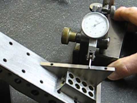
The traditional method of measuring angularity uses a sine plate. The feature under inspection is tilted to the basic angle in the drawing so that it is horizontal, and therefore, parallel with the granite slab. The machinist then checks whether the flatness of the surface is within permissible limits using a dial gauge.
