

ASME Y14.5-2009 outlines 14 different types of geometric tolerances. Each of those tolerances specifies a type of control over various part features. For ease of understanding, these 14 types can be segregated into five main groups. These are form, profile, orientation, location and runout.
Location controls maintain tight control on a feature’s position with respect to a datum. Concentricity, symmetry and true position are the controls under the location category. In this article, we shall take a look at concentricity, its various aspects, uses and measurement methods. Let us start by defining concentricity.
What is Concentricity?
Many mechanical parts require a highly accurate concentric design for a satisfactory operation. Parts such as tubes that endure high pressures require a design with uniform wall thickness to prevent any weak structural points. Concentricity is a 3D GD&T callout that ensures that one or more part features are concentric about a datum axis.
However, in GD&T, concentricity has a slightly different meaning than the literal definition that most engineers are aware of. The function of concentricity callout is to ensure that the midpoint of two diametrically opposite points lies within a specified tolerance zone. The circular feature may have notches, dips or other surface variations but the mass distribution about the central axis should be uniform.
This balanced mass distribution is important in applications where the part undergoes high-speed rotation and there is a risk of oscillation or uneven wear. But concentricity is a difficult characteristic to achieve and measure during manufacturing.
In most applications, simpler callouts such as circular runout, total runout, position or profile can do the job equally well. Wherever possible, they must be used to avoid concentricity.
Concentricity Tolerance Zone
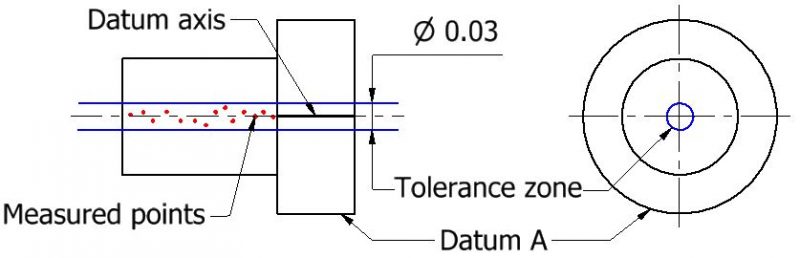
The zone for GD&T concentricity is a cylindrical tolerance zone. The feature control frame specifies a datum axis that is used as a reference point to develop this zone. The diameter of this cylindrical zone is the permissible tolerance value for the callout.
In order to ensure concentricity, the actual median axis for the part must be derived by calculating midpoints of diametrically opposed points. When all such median points are connected, we obtain the median axis. All the points on the median axis must lie within the cylindrical tolerance zone for the approval of the part.
Concentricity vs Other Callouts
Concentricity is a necessary callout in many specialized applications where a uniform mass distribution is of the utmost importance. But due to the difficult and costly process involved in its application, it is important to be aware of other callouts that can replace concentricity without compromising the required specifications.
Circular runout and true position (also sometimes known as ‘position’) are the two most closely related callouts that can replace concentricity in many applications.
Concentricity vs Circular Runout
The difficulty in measuring concentricity arises from the need to find the derived median axis of the part. There is no method in which such a calculation can be carried out reliably without the use of a computer.
On the other hand, the runout of a part can be measured easily from the surface since it is a tangible feature. Moreover, simple instruments such as a V-block and a dial indicator can give reliable runout measurements.
Runout is popularly defined as the sum of circularity and concentricity. If a part is perfectly round, runout tolerance becomes equal to concentricity tolerance.
Specially designed gauges can also measure runout in a quick (<10 seconds), effective and relatively inexpensive manner. Thus, from all angles, runout is a better alternative to concentricity and must be used wherever possible.
Concentricity vs True Position
True position in GD&T is a fairly simple callout that can fix the position and size of different features. In many cases, true position callout can effectively replace concentricity. Standard hole sizes and positional tolerances are better than concentricity when there is no need for a precise mass distribution.
- Personal account manager
- Quality assurance
- Payment terms for companies
- On-time delivery by Fractory
Concentricity Feature Control Frame
We use feature control frames (here on out referred to as ‘FCF’) to explain the manufacturing conditions, controls and tolerances placed on a part feature. A single part may have multiple features toleranced by GD&T. Each feature’s tolerance is represented by its own FCF. The FCF connects to the feature under control or its extension line using a leader arrow.
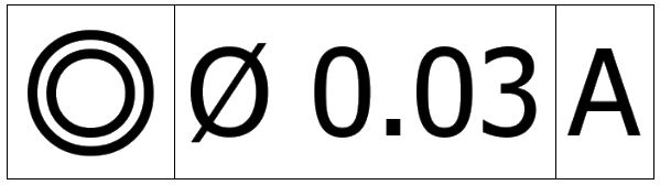
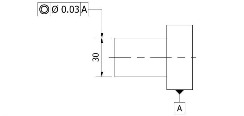
The feature control frame for GD&T concentricity is pretty straightforward. It follows the general layout of an FCF which consists of three distinct blocks. The blocks for concentricity can be understood as “relative to datum A, all median points of opposing elements on this cylindrical surface must lie within a cylindrical tolerance zone of 0.03”.
Each block gives information about a different aspect of the GD&T tolerance. These three blocks are:
- Geometric characteristic block
- Feature tolerance block
- Datum block
Geometric characteristic block
This is the first block in the concentricity FCF. It contains the symbol of the geometric tolerance applied to the feature. The concentricity symbol consisting of two concentric circles is placed in this block to specify this tolerance.
Feature tolerance block
This is the second block in the FCF which provides information about the type and size of the applied tolerance zone.
In the case of concentricity, the zone’s shape is cylindrical. This zone is also known as a diametral tolerance zone and is specified using a diameter symbol in this block. The diameter of this cylindrical zone is the tolerance value or the maximum allowable deviation for the derived median points of the part.
Material modifiers cannot be used with concentricity as the bonus tolerance would come into the picture. This extra tolerance enlarges the tolerance zone which leads to a step function of varying diameters, causing sharp changes in the surface diameter.
Datum block
This block contains information about the datum element. It may be a center point, a center line or a datum plane depending on the requirement. In the case of concentricity, the datum element is a datum axis derived from a datum feature. Sometimes, concentricity FCF may contain multiple datums. That is the case with shafts with multiple diameters.
How to Measure Concentricity
The procedure for measuring concentricity is the prime reason why most designers and machinists choose to avoid it. Taking necessary measurements is difficult, time-consuming and costly.
The inspector needs to build the actual central axis of the part by joining the center points of successive circular cross-sections. This is why a reliable concentricity measurement requires the use of a coordinate measuring machine (CMM) or some other computer-aided measuring method such as an optical shaft measuring system or a laser micrometer with a concentricity extension.
In many cases, engineers record the difference between the highest and lowest point on the surface using a dial gauge. They are under the impression that they are measuring concentricity when they are actually measuring runout. As we saw earlier that for runout to be equal to concentricity, the section under observation must be a perfect circle, which is rarely the case. Passing runout measurements as concentricity allow circularity errors to creep into the concentricity tolerance.
Now, let’s take a brief look at the step-by-step process to measure concentricity.
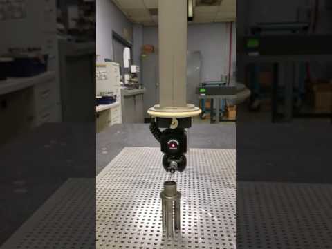
Measuring concentricity using a CMM
ARVE error: url: https://www.googleapis.com/youtube/v3/videos?part=snippet%2Cstatistics&id=DX6xRfe3ZrU&key=AIzaSyAQ7WFzTAUrOX-FjsIrFS3JwZBFzgIvloc Status code 200 expected but was 403.
The concentricity tolerance can be measured using a CMM in four distinct steps:
Step 1: Securing the part and fixing the datum axis (theoretical axis)
The first step is to lock all degrees of freedom by constraining the part in a suitable position. The position must allow access to the entire cylindrical surface for measurement. This ensures that there is no need for repositioning during the whole course of taking measurements.
Then we need to establish the datum axis. We recommend choosing the bearing end of the shaft for the datum axis as the rotation of the assembly will be directed from that end.
Step 2: Finding the center point for one cross-section
The second step is to plot the control surface using a CMM stylus. We need multiple pairs of diametrically opposed points at each cross-section of the cylindrical part. A minimum of three such pairs is recommended at every cross-section. For these three pairs, we might receive three distinct median points (unless some coincide). The average of those three median points is selected to determine the center point for the cross-section.
Step 3: Repeating for multiple cross-sections across the cylindrical part length
The center point for multiple cross-sections must be calculated. On joining these points, we obtain the measured axis or the actual central axis of the part. This axis is also known as the derived axis.
Step 4: Check whether the measured axis lies within the tolerance zone
After obtaining the measured axis of the cylindrical (or spherical part), we check its position in reference to the datum axis. Each point on this axis must lie within the cylindrical tolerance zone specified in the FCF.
Uses of Concentricity
Most professional engineers understand that the concentricity tolerance must not be used unless absolutely necessary. But there are still many applications that require it. Some of these are:
- Precision ball bearings
- Transmission gears
- Medical-grade tubing
- High pressure piping
Precision ball bearings
These are high precision parts used in a variety of industries to reduce energy losses. Their manufacturing must achieve tight tolerances for a satisfactory operation. Concentricity tolerance is used between various elements of a ball bearing to ensure it meets specifications.
Transmission gears
The manufacturing of transmission gears requires concentricity to line up the axes perfectly. This prevents sideways movement and minimises wear rate. However, in some cases, runout may provide enough accuracy.
Medical-grade tubing
Concentricity is also used to control the tubing wall thickness in medical devices. These parts can be tiny and require high precision for an acceptable product.
High-pressure piping
Quite often, high-pressure piping may be manufactured using concentricity tolerance. These parts require a minimum wall thickness to prevent any thin points along the length where the tube may rupture due to the high pressures.
FAQ
Has concentricity been removed from ASME Y14.5-2018?
Yes, the 2018 ASME standard does not include concentricity tolerance. However, this isn’t very shocking as all previous versions also recommended using position and runout wherever possible. Besides, the majority of companies still use the 1994 standard while the remaining use the 2009 version. Thus, concentricity controls can still be used, unless the previous versions are restricted.
What is eccentricity?
Eccentricity is the measure of the offset with respect to the geometric center of the tube profile. It is a vector quantity with magnitude as well as direction. Quite often, the value of eccentricity is found to be half that of concentricity.
The magnitude of eccentricity is calculated as:
Eccentricity = (maximum wall thickness – minimum wall thickness)/2
