

Mechanical engineers learn a list of rules to follow when making engineering drawings. Those rules don’t always apply, though. When making drawings for automated cutting jobs, they have to be very simple.
What are the things to keep in mind when making production drawings? We have compiled a list of tips for engineering drawings:
DXF is the Right Choice
DXF files can be fed straight to CNC machines. Always prefer DXF to DWG or any other file type. There is also free CAD software for making 2D drawings in DXF format. DXF files can also be used to get instant laser cutting quotes.
Create a Drawing from Scratch
Don’t use the save as command to create a new drawing. Start a new one instead. Otherwise, you can end up with a faulty drawing. We see ones that have leftover lines or views from old drawings laying around. This can lead to 36×20 metre sheet sizes and the like.
Also, blocks and layers that are not related to the drawing make simple flat pattern files unnecessarily big (e.g 1.5 Mb). This slows down the uploading process.
Chamfered Holes
Plasma and laser cutting are for perpendicular cuts only. Add the required chamfers later. The manufacturing drawing should include the cutting line for the hole, nothing more. Show the chamfers on a separate PDF and add it to your quotation request.
Threaded Holes
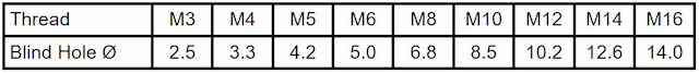
Threading is an extra operation. You can still cut a blind hole into the sheet with a laser to make the threading effortless and accurate.
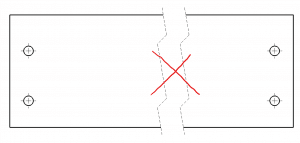
Leave Room Between Cuts
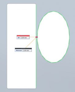
Leave some room between two cuts. If they are too close, the metal melts and may spray around, leaving an ugly area between the holes. Even worse, the bridge may melt altogether, if it is very narrow. The rule is to leave a bridge as wide as the thickness of the material.
Small Holes
Holes with a diameter smaller than the thickness of the plate must be drilled after the cutting process. Our advice is to adjust the size if possible to keep the costs low. Otherwise, the price of drilling gets added later. If you really need holes that small, you can get the centre marks engraved to ensure accurate positioning.
One Part per Drawing
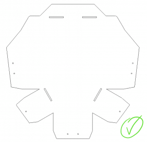
Delete anything that isn’t necessary. If you submit a collage of 20 details, someone will have to copy them onto separate drawings manually. Do it before uploading the drawings to get the fastest possible laser cutting service. No side-views or anything, just a flat pattern.
Hatched Holes and Centre Lines
You may ask yourself – who hatches holes? Someone. This is neither a standard, nor useful in any way. We were all taught to mark holes with centre lines in our classes but those are also just a distraction. Keep it blank.
Connect the Letter Insides

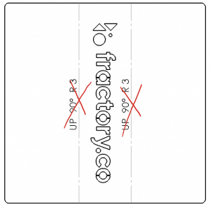
This is very often overlooked. When you want to add some words on your sheet of metal, consider the fact that the insides cannot levitate in the air. In our example, the inside ring of “O” is connected by 2 bridges. Otherwise, the inside ring would fall away and there would be an extra cut unnecessary to the final outcome.
Laser Cutting Leaves an Inside Radius

So, the last example was almost good. Still, you cannot make sharp cuts. A laser beam itself is round, thus leaving an inside radius. The simplest way is to follow material thickness – the minimal inside radius is 1/10 of the thickness. As an example, you can use R1, if you have a 10 mm thick steel plate.
Check the Scale
All drawings must be 1:1. Check the scale after creating the DXF files. Our system gives your sheet’s general dimensions after uploading the drawings. Make sure it corresponds to reality. If not, adjust the scale.
Overwriting Dimensions
We receive engineering drawings that have overwritten dimensions on them. If you just delete the old value and replace it with the right one, the scale will still stay the same. The dimension does not drive the line length.
Breaking the Views
Breaking a view may be a useful tool to make a drawing easily readable for a person. However, engineering drawings heading to automated cutting are read by computers. Breaking a detail gives the opposite effect and confuses the system, so forget about this function for now.
Glitches, Errors and the Like
This is especially common when converting the drawing format (e.g. PDF to DXF). Check the converted one for scrambled lines, random dots etc. If it keeps occurring, some Googling may lead you towards solving the problem. All my bolted connections used to show up scrambled, a 2-minute tutorial saved me from manual labour.
Nice Side Up
The prettier side of the sheet must be facing you. If you choose to get your sheet metal brushed, include the direction of brushing on your PDF drawing. Otherwise, you can orientate your DXF knowing that the brushing will be done horizontally in relation to the drawing.
Infinite Coastline
The coastline paradox says that the coastline of a landmass has no definitive length. Coastlines have fractal-like properties that lead to infinite lengths. We have received similar drawings that have zig-zaggy lines. Our calculator gives the price accordingly, although the zigginess of the lines is a mishap.
No Title Block
Title block is another confusing element for the computer. Only include lines that are used for cutting. The system does not care who is the author of those drawings, nor who checked them.
Overlapping Lines
We have received engineering drawings that have lines on top of each other. You may not notice them but the computer does and calculates them as separate cuts, adding to the price quotation. You will not be charged for those cuts later but the initial price will not represent the reality.
Bending Lines
The same applies for bending lines. They are not related to cutting but will be seen as lines to cut, thus adding to the price offered. Add those to your PDF or just upload a .STP file for sheet metal bending. When using SolidWorks or Autodesk Inventor, you don’t have to convert your files to .stp as our platform also supports file formats native to these software (.sldprt and .ipt respectively).
Also, make sure that it is possible to manufacture your design with the available press brake tooling.
Everything Must Be Connected
If you draw in a 2D environment, like AutoCAD, connect all the lines on the drawing. One way for an easy check is to try to hatch an area – if it is not properly connected, the hatch cannot be done. Just don’t forget to delete the hatched area after a successful try!
Cut to Normal
As stated before, laser and plasma cutting are for perpendicular cuts only. If you design a product in a 3D CAD-software and want to cut a hole in a shallow cylinder, use the function cut to normal to avoid confusion. This results in cuts that are marked with one continuous line.
The points above will shorten your time spent on drawing. Remember to keep it simple. It may be difficult to abandon all the drawings rules taught at university but it will make the service smoother for everybody.
Following this advice will give you quick and accurate quotations for your details!
