

There are 14 types of geometric tolerances in GD&T according to ASME Y14.5-2009. These 14 tolerances can be categorized into five main groups: form, profile, orientation, location and runout.
Perpendicularity is a type of orientation control. Orientation controls define the orientation of a feature with reference to a datum plane or axis. Angularity and parallelism are other callouts in orientation control besides perpendicularity.
This article will explain the various aspects of perpendicularity and its two types in detail.
What Is Perpendicularity?
Exact perpendicularity between features is very difficult to achieve. The perpendicularity callout establishes limits within which a feature must lie to be accepted as reasonably perpendicular.
Similar to GD&T straightness, there are two ways in which perpendicularity may be applied. It can control the perpendicularity of a surface or an axis. Let us explore each type.
- Surface perpendicularity
- Axis perpendicularity
Surface Perpendicularity
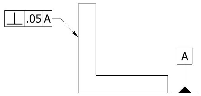
Surface perpendicularity is a 2-dimensional GD&T callout that controls the perpendicularity between two surfaces. The surfaces must be perpendicular within the tolerance limits specified in the feature control frame. Surface perpendicularity does not directly control the angle between the surfaces. Instead, it ensures perpendicularity by defining the location where the surface must lie for approval.
Axis perpendicularity
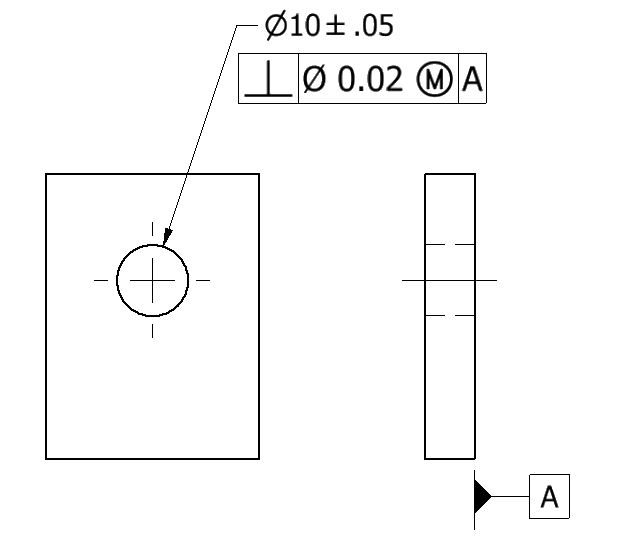
Axis perpendicularity ensures that the axis of a feature is within the perpendicularity limits in the feature control frame (FCF). The feature may be positive such as a pin, or negative such as a hole.
Axis perpendicularity is a 3D tolerance that specifies a cylindrical boundary where the axis of the referenced feature must lie.
Perpendicularity Tolerance Zone
As with all other GD&T callouts, the perpendicularity callout sets up a tolerance zone at the ideal location of the feature. The zone particulars, however, are different for surface and axis perpendicularity.
Let us see how these two zones work and the differences between them.
Surface perpendicularity tolerance zone
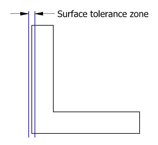
The tolerance zone for surface perpendicularity is made of two parallel planes. The surface under inspection must lie in between the two planes for approval. The feature control frame controls the spacing between the two planes—the smaller the spacing, the tighter the zone.
As it is apparent from the shape, the zone does not directly control the angle between the two surfaces. Instead, it creates a zone perpendicular to the datum surface and maintains the flatness of the perpendicular surface.
Axis perpendicularity tolerance zone
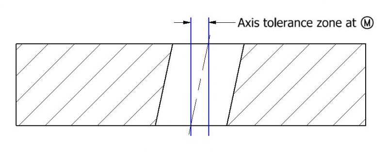 For axis perpendicularity, the tolerance zone is cylindrical. The zone is created around a theoretical axis that is perfectly perpendicular to the datum feature. All the points on the feature’s actual axis must lie within the zone for approval.
Since the zone is cylindrical, the feature control frame contains a diameter symbol to denote it.
Perpendicularity vs Other Callouts
The perpendicularity callout symbol bears some similarities to other commonly used GD&T callouts. This section covers some of those callouts.
Perpendicularity vs Flatness
Similar to flatness, surface perpendicularity measures surface variation between two parallel planes. But unlike perpendicularity, flatness (like all other form controls) applies to a surface without a datum.
Another difference is that perpendicularity controls the angle (90° with respect to the datum feature) while flatness does not. Flatness is only concerned with the smoothness of a surface and the angular variation from the desired range does not make any difference.
Perpendicularity vs Angularity
All orientation controls are similar to each other in a way. Perpendicularity is a specialized form of angularity, as is parallelism. While angularity can maintain orientation at any specific angle, parallelism and perpendicularity are set at 0°/180° and 90° respectively.
- Personal account manager
- Quality assurance
- Payment terms for companies
- On-time delivery by Fractory
Perpendicularity Feature Control Frame
The feature control frame (FCF) for perpendicularity is pretty straightforward. The leader arrow of the FCF points to the feature under control or its extension line. Compared to an axis, there are some minor differences when perpendicularity is applied to a surface. This section will explain the FCF for perpendicularity in both cases.
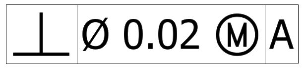
To understand the FCF better, we shall divide it into its constituent blocks as follows.
- Geometric characteristic block
- Feature tolerance block
- Datum block
Geometric characteristic block
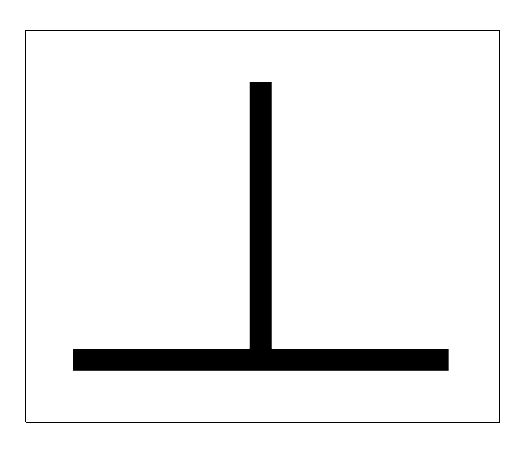
The geometric characteristic block houses the GD&T symbol for the geometrical tolerance. Perpendicularity symbol is ⊥ and it is used for both surface and axis perpendicularity.
Feature tolerance block
The feature tolerance block contains information about the shape and size of the tolerance zone and any material condition modifiers in that order.
If no symbols are present for the zone’s shape, total wide tolerance zone is considered as the default. This is the case for surface perpendicularity.
In the case of axis perpendicularity, a cylindrical tolerance zone must be indicated. To denote this, the feature tolerance block contains a diameter symbol in front of the tolerance value.
This symbol is followed by the tolerance value or limit that defines the width of the tolerance zone.
When it comes to material modifiers, perpendicularity is often called with either MMC (Maximum Material Condition) or LMC (Least Material Condition). If LMC/MMC symbols are not present, the reader understands that the default condition of Regardless of Feature Size (RFS) is in use.
Datum block
The datum block contains information about datums used as a reference for the feature under control. Orientation controls cannot function without a datum. For perpendicularity, we often associate a surface as a datum. This surface’s name is placed in the datum block.
At times, multiple datum surfaces may be used. These datums are placed one after the other and are referred to as primary datum, secondary datum and so on.
For example, let’s say we need to design a cube-shaped product and the base and the first wall have tolerances already applied. We can use the perpendicularity callout for the adjacent wall.
To ensure that the second wall is perpendicular to the base and the first wall, we use both of them as datums in the perpendicularity callout.
How To Measure Perpendicularity

ARVE error: url: https://www.googleapis.com/youtube/v3/videos?part=snippet%2Cstatistics&id=o_Z2bjYufxk&key=AIzaSyAQ7WFzTAUrOX-FjsIrFS3JwZBFzgIvloc Status code 200 expected but was 403.
Both surface and axis perpendicularity are relatively easy to measure when comparing them to other GD&T callouts.
Let us see how this is done.
Surface perpendicularity measurement
Measuring surface perpendicularity requires the use of a height gauge. The datum surface is kept in contact with a surface plate during the measuring process.
The degree of freedom of the gauge (or the part) is restricted by only allowing relative motion in the perpendicular direction. The deviation on the height gauge’s dial gives the perpendicularity of the feature.
Axis perpendicularity measurement
Axis perpendicularity is usually measured with custom gauges. These gauges are built with keeping the Virtual Condition of the feature in mind.
Axis perpendicularity is often called out at MMC to ensure a good fit in all cases. Bonus tolerance also plays a role in defining the range of sizes that will pass the tolerance check.
Uses of Perpendicularity
Perpendicularity is a very common callout in GD&T due to its simplicity and usefulness. Both surface and axis perpendicularity are often used in engineering drawings to guarantee the desired perpendicularity.
In its surface form, perpendicularity can control planar as well as curved surfaces. For instance, it can ensure the perpendicularity of a cylinder’s curved surface with respect to the cylinder’s bottom. It may also be used for centre plane tolerancing.
In its axis form, perpendicularity can control the centre axis of various positive and negative features. It is predominantly used to ensure the perpendicularity of holes and pins to make sure they mate perfectly in an assembly.
Bonus Tolerance in Perpendicularity
Bonus tolerance refers to the increase in allowed tolerance limits as the size of a positive feature shifts from the MMC condition towards the LMC condition. Let us explain this with a simple example.
Imagine that two pipes need to be connected by flanges. The faces must be perpendicular to the pipe length. The pipes are usually manufactured at their MMC to fix the Virtual Condition (VC) size. This size represents the maximum allowed size for the pipe, inclusive of the perpendicularity tolerance.
But as we depart from the MMC size of the pipe, the outer diameter reduces and it does not have to be as perpendicular to the flange face as before to fit into the flange bore.
Thus, the reduction in pipe diameter translates into increased flexibility (or tolerance) in perpendicularity. This increased allowable tolerance is the bonus tolerance. In other words, it is the extra tolerance on top of the perpendicularity tolerance limit mentioned in the FCF.
