

ASME Y14.5 2009 GD&T Standards lists out 14 types of geometric tolerances. These 14 tolerances are bunched up into five different groups based on the type of control they offer. Among these five groups is runout control.
It is a type of combination control (the other being profile control). Combination controls affect more than one feature of a part such as orientation, location, size and/or form.
There are two types of runout controls:
- Runout or circular runout
- Total runout
In this post, we shall learn about circular runout.
What is Circular Runout?
Circular runout, commonly known as just ‘runout’ is a 2D measure of a circular profile in relation to a datum axis. It inspects how well a circular cross-section conforms to a perfect circle much like circularity.
The question then arises: Why do we need another callout to check the circular profile when we already have the circularity callout?
The circularity callout does check the circularity of a feature, but it does not do so in reference to a datum axis.
So, a surface that is perfectly round would meet the circularity callout even if it is off-centred. This could, however, cause the part to wobble when it rotates during service.
Circular products that require close tolerances or rotate at high speeds must rotate around the central axis besides being as circular as possible to prevent errors in operation. Even a small wobble can significantly affect the functionality and reduce service life.
Circular runout helps us control and measure this wobble to ensure it is within permissible limits.
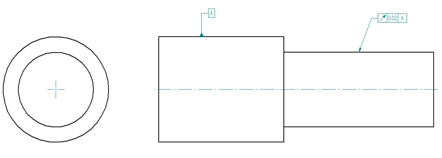
The datum axis acts as an anchor for the tolerance zone in circular runout. The callout creates a 2D circular tolerance zone around the specified datum axis. The ideal surface of the feature lies in this tolerance zone. In order to meet this callout, all points on the actual surface must lie in this zone.
Runout manages to specify everything necessary to avoid the wobbling effect without putting many different and too tight tolerances on the part.
Feature Control Frame of Circular Runout
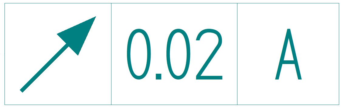
The feature control frame follows the same rules as it does with other GD&T symbols. The circular runout frame consists of three sections.
Circular Runout Symbol
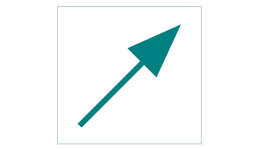
The runout symbol is a diagonal arrow pointing northeast (↗). It is a reference to how we measure the runout of a feature. We use a dial or height gauge to measure runout so the symbol actually represents the pointer in a dial gauge.
The runout symbol is placed in the first compartment of the feature control frame.
Tolerance limit
The tolerance limit makes up the feature tolerance compartment (2nd block) of the feature control frame. Note that the circular runout callout does not need the diameter symbol in the feature tolerance block.
The total variation on the dial gauge must be less than the stated limit.
Datum axis

As is often the case with GD&T, this is the most important part of runout’s FCF. Usually, we choose the central axis as the primary datum and mention it in the third block. But there are cases where we may choose a different axis as our datum.
Sometimes, the primary datum is the surface of the circular feature. Other times, it may be the plane perpendicular to the central axis.
In rare cases, two datums may be combined and used as a primary datum instead of one being primary and the other being the secondary datum.
- Personal account manager
- Quality assurance
- Payment terms for companies
- On-time delivery by Fractory
How to Measure Circular Runout?

Runout is measured using a simple height or dial gauge. We fix the part by means of a V-block or a spindle along its datum axis. The pin of a dial gauge is then set on the circular feature and the dial is set to zero.
We now rotate the CNC machined part along the spindle and record the measurements. The total variation on the height gauge must not exceed the tolerance limit in the feature control frame.
We can measure runout for surfaces that are parallel, angled, or perpendicular to the axis. In all cases, we hold the height gauge perpendicular to the surface. For each case, a two-dimensional tolerance zone is created in the direction of the height gauge pin. Then, as many cross-sections as needed are tested.
For surfaces that are perpendicular to the datum axis, we are testing flatness rather than circularity when we use this callout.
When using it for angled surfaces, we must remember to mention the basic angle, so we can set the height gauge exactly perpendicular to the surface.
Use-Cases
As mentioned before, we use circular runout for rotating parts to prevent any wobble in the final assembly. Examples of such parts include drills, axles, gears, shafts, etc. To identify whether runout will be effective on a part, the criterion we set is as follows.
There are three types of parts that circular runout can control effectively. If the parts have one of the following three features, we use total runout control or we opt for something more appropriate.
Parts with a high length-to-diameter ratio
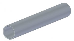
Parts with such a profile (a metal tube for instance) can be fixed into place easily and rotated to check the profile.
Sufficient length is critical in ensuring the degrees of freedom (DoF) are restricted as needed for an accurate inspection. This is the ideal part for which runout is most effective.
Parts with a small diameter and a perpendicular plane

In case the part has a short length and small diameter but is accompanied by a perpendicular plane (a flange for instance), circular runout can help us inspect the accuracy of the part.
In such a case, we cannot use the central axis as the primary datum as it will not be able to effectively constrain the required degrees of freedom for inspection.
So we set the perpendicular plane as the primary datum and the central axis as a secondary datum. Such parts are held with an expanding chuck to rotate the part.
Parts with multiple small diameters far apart from each other
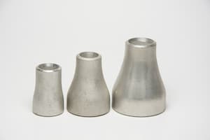
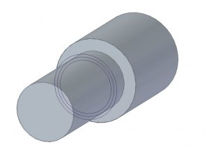
An example of such a part is a concentric pipe reducer. In such a part, there are multiple short diameters at the extreme ends of the part. Both the datum axes are combined and used as the primary datum instead of one being used as a primary and the other as a secondary datum.
For example, if A and B are the short axes at the ends of the part, then they may be used simultaneously to inspect other central part features by combining A and B in the datum block as |A-B|.
Why Use Circular Runout?
As mentioned earlier, circular runout is a combination control, determining a combination of features for a part. Using circular runout, we can control location, orientation, and form in two dimensions.
An exception occurs when the size tolerance is stricter than runout tolerance. In such a case, size tolerance controls the form of the feature. Using just this one callout, we can control the following physical characteristics.
Circularity
The callout controls the circularity of the inspected cross-section. We can inspect the circularity of the entire product by selecting multiple cross-sections since runout is a 2D callout and can focus on only one cross-section at a time.
Coaxiality
Since the part held by the chuck and the feature being inspected rotate along the same axis, runout also controls the coaxiality of both features. This indirectly ensures that all inspected features are coaxial with each other.
Concentricity
Runout can also measure concentricity for a product. ASME Y14.5 defines a part as concentric when the median points of at least three pairs of diametrically opposed points lie on the central axis for a considered cross-section.
The concentricity of a cross-section is the smallest circle around the central axis within which all the medians of all diametrically opposed points of a cross-section lie.
In the case of the runout feature, all the surface points lie within a narrow, circular tolerance zone. As a result, the median of any pair of diametrically opposed points of the considered cross-section also lies within a narrow zone around the central axis.
In fact, runout does not just compare diametrically opposite points. It compares the extreme variations of a surface and keeps them under the tolerance limit. So in a way, runout is a better measure of concentricity, and machinists will often use it as a sanity check for concentricity.
Derived median line (DML) straightness
If we extend the above concentricity inspection over the length of the product, we get a line formed by the medians of all the cross-sections. This is because all cross-sections are centred along the same central axis.
Thus, when extended over the entire length, this callout also controls the straightness of the derived median line.
Flatness
Runout also controls the flatness of the features that are perpendicular to our primary datum. This is because we measure the plane by holding the gauge pin perpendicular to the annular ring surface parallel to the datum axis.
So any deviations on the dial gauge will be indicative of surface irregularities. Fewer deviations on the dial gauge represent a flatter surface.
All the above-mentioned characteristics are important features of a product to ensure proper assembly and function. It is possible to use different callouts to check each of the features. But it does not make sense to use these many callouts on our drawings. Each separate callout would also bring into play its own inspection method.
We avoid this by using circular runout and its inspection method to ensure that all the above features are kept within permissible limits with just one callout.
Circular Runout vs Total Runout
In simple terms, total runout is the 3D equivalent of circular runout. While circular runout forms a circular tolerance zone around the surface (2D), total runout forms a cylindrical zone.
Besides placing tolerance limits on a cross-section, total runout places it along the entire cylindrical surface to control all cross-sections of the considered feature at the same time. Thus, it accounts for axial variations along with cross-sectional variations.
Total runout helps us control more characteristics than circular runout. It is capable of controlling surface characteristics such as:
- Circularity
- Coaxiality
- Concentricity
- Straightness
- Cylindricity
- Taper
- Parallelism
- Angularity
- Perpendicularity
- Profile

The inspection process for total runout is also a bit more complicated. Similar to circular runout, we use a height gauge to inspect total runout.
In circular runout, we rotate the part along the specified datum and record the changes on the height gauge.
In addition to rotating the part, we move the height gauge along the datum axis to measure axial deviations in total runout. If the gauge readings do not vary more than the total runout tolerance, the part is in spec.
In many cases, a CMM inspects the total runout of a part for accuracy.
Total runout is not used as commonly as circular runout as it puts a lot more restrictions on surface characteristics. But it still finds usage especially for products demanding high accuracy and/or rotating at high rpm. Examples include pump shafts and automobile transmissions.
Important Points to Remember
- Circular runout requires a datum, unlike circularity. So remember to mention the datum on your callout.
- Circular runout is always understood as a 360° rotation around the datum axis and hence, is used without a diameter symbol in the feature control frame.
- Runout is a surface control and not a feature of size control. As such, it is always called RFS (Regardless of Feature Size). Material condition modifiers or bonus tolerances are not used with circular runout.
Conclusion
Runout is a widely used symbol to ensure our products mate well and function as needed. It controls many surface characteristics while being easy to inspect. In fact, it is easier to inspect than certain other callouts that are not even as versatile, e.g. concentricity.
This post would be incomplete without us using the famous quote about runout, “When in doubt, use runout.”
