

CNC milling is one of the most common processes when looking to produce complex parts. Why complex? Whenever other fabrication methods like laser or plasma cutting can get the same results, it is cheaper to go with them. But these two do not provide anything similar to the capabilities of CNC milling.
So, we are going to take a deep dive into milling, looking at the various aspects of the process itself as well as the machinery. This will help you understand if you require CNC milling services to produce your parts or if there’s a more cost-effective alternative available.
What is CNC Milling?
We are going to look at the process, machinery, etc. in later paragraphs. But let’s first make clear what CNC milling means and bring clarity to some of the more confusing points about the term itself.
First, people often ask for CNC machining services when looking for milling. Machining entails both milling and turning but these two have distinct differences. Machining refers to a mechanical cutting technology that uses physical contact to remove material, using a wide range of tools.
Secondly, all CNC machining uses CNC machines but not all CNC machines are for machining. Computer numerical control is what lies behind these three letters. Any machine using CNC utilises computerised systems for automating the cutting process.
Therefore, CNC machines also include laser cutters, plasma cutters, press brakes, etc.
So CNC machining is a mix of these two terms, bringing us the answer to the question posed in the heading. CNC milling is a subtractive fabrication method that uses computer numerical control systems for automating the process.
Milling Process
We could limit ourselves to describing the fabrication process only but giving an overview of the complete flow gives a more wholesome picture.
The milling process includes:
- Designing the parts in CAD
- Translating the CAD files into code for machining
- Setting up the machinery
- Producing the parts
Designing the CAD files & translation into code
The first step is creating the virtual representation of the final product in CAD software. There are many powerful CAD-CAM programs that let the user create the necessary G code for machining.
The code is available for checking and amending, if necessary, to suit the machine’s capabilities. Also, manufacturing engineers can simulate the whole cutting process using this kind of software.
This allows checking for mistakes in the design to avoid creating models that are not possible to produce.
G code can also be written manually, as was done in the past. This, however, prolongs the whole process considerably. Therefore, we would suggest making full use of the possibilities modern engineering software offers.
Setting up the machine
Although CNC machines do the cutting work automatically, many other aspects of the process need a machine operator’s hand. For example, fixing the workpiece to the worktable as well as attaching the milling tools to the spindle of the machine.
Manual milling depends heavily on the operators while newer models have more advanced automation systems. Modern milling centres may also have live tooling possibilities. This means they can change the tools on the go during the manufacturing process. So there are fewer stops but someone still has to set them up beforehand.
After the initial setup is done, the operator checks the machine program one last time before giving the machinery a green light to start.
- Personal account manager
- Quality assurance
- Payment terms for companies
- On-time delivery by Fractory
Production work
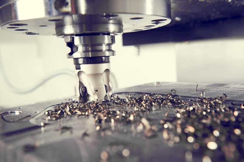
The milling process uses a rotating tool that comes into contact with the workpiece to cut off chips. The continuous cutting results in the desired shape.
There are, however, a few different ways to perform the cutting:
- Conventional milling
- Climb milling
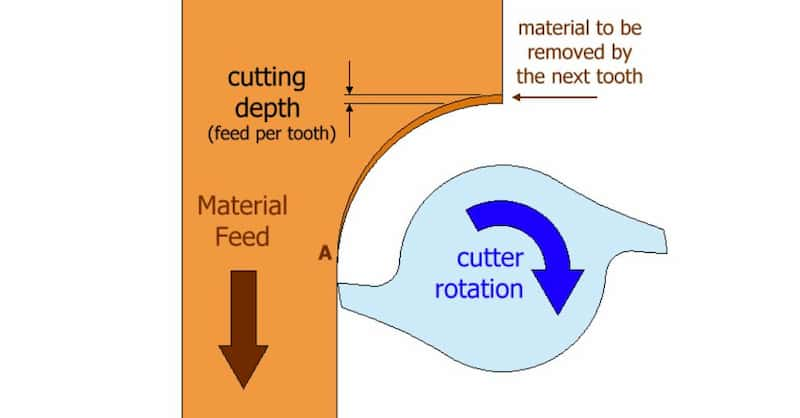
As the name says, conventional milling has been the more common way to mill, at least in the past. The mechanics of conventional milling:
- The cutting chip increases in thickness. This can cause elevated temperatures that produce work hardening.
- The beginning of a cut includes more rubbing and friction, quickening the tool wear and shortening its lifespan.
- As the teeth carry chips upwards, they may fall back into the cutting path, decreasing the quality of the finish.
- Tighter clamping and fixing of the workpiece is necessary to avoid displacement caused by the large upwards forces.
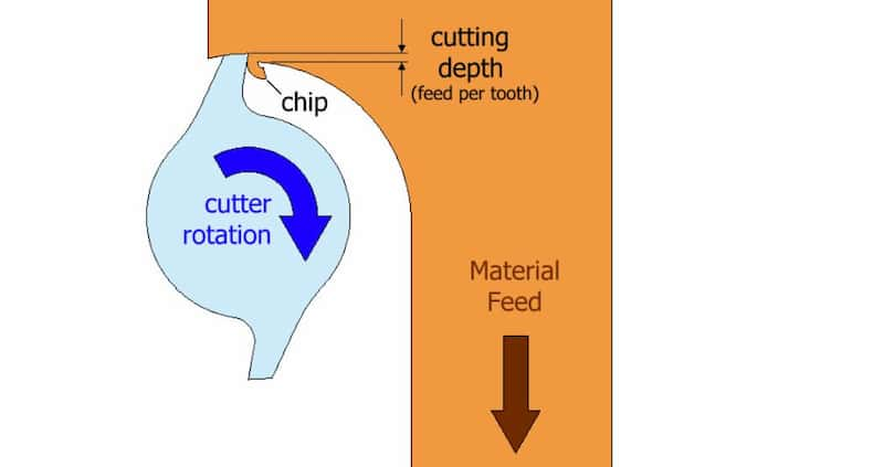
Newer CNC mills rather use climb milling. The features of climb milling are:
- The cutting chip decreases in thickness, causing heating of the chip rather than the workpiece.
- The cutting surface is cleaner, resulting in less rubbing and an increase in tool lifespan.
- The chips fall behind the cutter, reducing the problem of a polluted cutting path.
- Horizontal climb milling creates downward forces, reducing the necessity for extra clamping.
The milling process usually comprises of a few different operations but this depends on the shape of the final product and the state of the raw piece. Often, milling is necessary for giving a precise finish and adding a few features like slots or threaded holes.
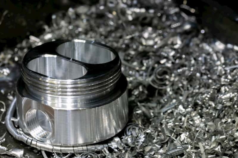
But it is also suitable for creating a finished part from a block of material. The first operations use larger tools to quickly carve away the material to fasten the process until getting to an approximate shape of the final piece.
A tool change is necessary to create highly accurate machined parts. The great precision milling is known for is achieved in the last stage, taking engineering tolerances and surface roughness to levels hard to match with any other fabrication process.
Milling Machine Components
Now, let’s see what makes up a milling machine. While new milling centres have the capabilities to perform all kinds of operations, they are also more complicated. So we are sticking to the more traditional benches here to give an overview of the machine components.
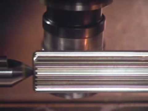
Horizontal milling machine
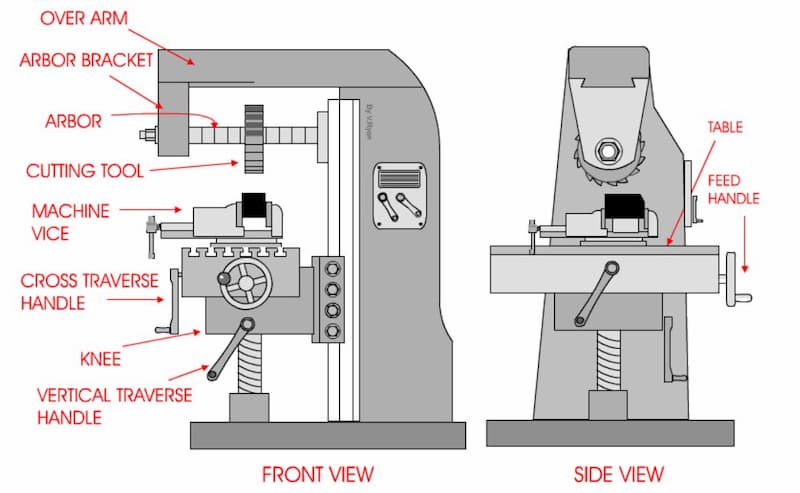
Horizontal milling machines derive their name from the positioning of the tool – their axis lies horizontally. The images above show one way of using them which is plain milling. Of course, horizontal mills are also suitable for end milling.
The build of a horizontal mill is pretty simple. The cutting tool attaches to the arbor. When a change of tooling is necessary, you can remove the arbor bracket and the spacers to replace the tools.
Fixing the workpiece onto the working table requires a vise. The traverse can move the table on X, Y and Z axis for moving the workpiece.
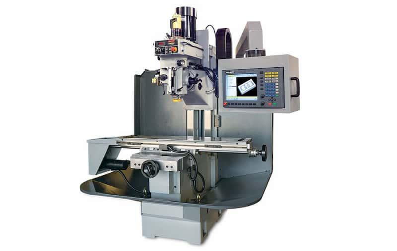
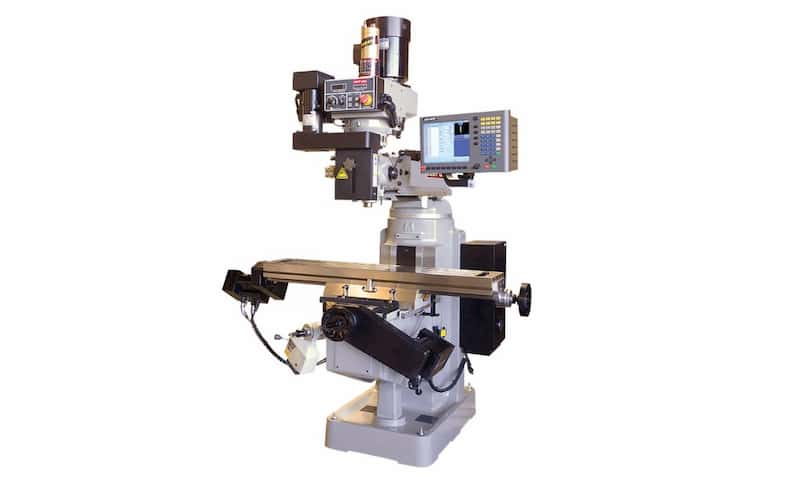
Of course, newer machines look a little different, making them suitable for automation. Horizontal milling centres may have several spindles with a variety of tools on them for quicker turnaround times. Also, the table as well as the tools can move in more directions, including rotational axes.
Still, the basics are the same and understanding the more traditional machine is enough to make sense of the contemporary ones.
The advantages of horizontal milling:
- Possibility to produce parts with fewer operations
- Ability to create more complex parts
- About 3-4x faster than vertical milling
- Longer tool life
- Better surface finish (the last 2 points are related to fewer chips falling onto the cutting path)
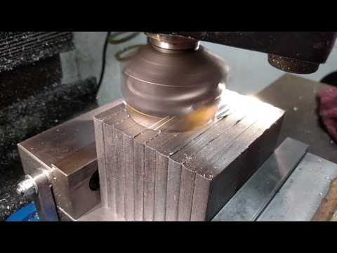
Vertical milling machine
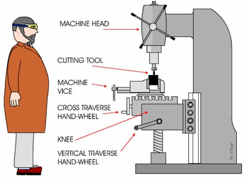
Again, the name of a vertical mill is pretty self-evident when looking at the image above. As the positioning of the tool axis is vertical, it is better suited for end milling.
There are a few differences between horizontal and vertical milling machines. But the main components are still similar. The machine head is at the end of a ram. The spindle for cutting tools is attached to the head.
Everything about the positioning of the table is identical to a horizontal mill, providing the ability to move it in the same 3 directions.
The modern 5-axis vertical mills offer possibilities to rotate the part for more access and faster turnaround times. Automating all the movements results in better accuracy, quicker lead times and close to identical batches of parts.
The advantages of vertical milling:
- Considerably cheaper than horizontal mills, with a price difference up to 4-5x
- Availability because more workshops can afford them
- Easier to use because the vertical mill provides better visibility of what is actually going on
- More machinists who can provide great results
- The machines are smaller, requiring less space in the CNC machine shop
Types of Milling Machines
There is a lot of variety available on the market today. Numerous ways of classification also exist. The basics remain pretty much the same everywhere, with a few modifications bringing about more possibilities and hence another type of milling machine.
Here are the most common types of milling machines:
- Bed-type
- Knee-type
- Ram-type
- Planer-type
Bed-type mills
The design of bed-type milling machines includes a stable machine bed. While large and heavy parts can result in instability with knee-type machines, bed-type ones can hold their ground. The long bed means that multiple parts can be attached to the bed at once, diminishing idle times and increasing the efficiency on the work floor.
The worktable attaches directly to the bed of the machine and can move in 2 directions. The spindle head, of course, can move axially to determine the cut depth. The position of the axis depends on the machine, as there are both horizontal and vertical bed mills, as well as universal machines. All of them can also be automated by using CNC.
The most common of these options is a CNC universal milling machine. While horizontal and vertical mills come with considerable limitations, these machines provide more flexibility.
Another way to increase productivity is using a two-machine stand. This helps to either mount a number of parts onto the table for simultaneous processing or one large part. This loses the necessity for re-clamping it to process the other end. It is important to note that this setup opens the possibility to tool collision which can be prevented by a correct CNC program.
Knee-type milling machines
These machines are suitable for producing parts ranging from small to medium size. The limitation comes from the fact that knee-type mills provide less stability than, for example, bed-type milling machines. Also, the frame sets its own limits for part dimensions.
A traditional knee-type mill is a great option for producing one-off parts, maintenance work, preparatory tasks, etc. The unidirectional movement of the cutting head limits the possibility of accidents. Using them for preparing the workpiece for later refining on a CNC station is common.
These machines require a manual change of tools after every operation, making the whole process a little slower. Still, modern CNC machining centres include the capabilities of knee-type milling machines.
Ram-type milling machines
The ram-type mill has its cutting head mounted on a ram that can slide back and forth. This increases the tool movement to 2 axes – X and Y. Both horizontal and vertical options of the ram mill are available on the market. Many of such mills also include the ability of swivelling the cutting head.
Planer-type mill
Planer-type mills are very similar to bed-type milling machines. Both have large worktables and spindles that can move in 3 directions. The main difference comes from the planer-type milling machines’ ability to accommodate more milling tools at once. The number of different tools usually goes up to 4.
Additional flexibility increases their efficiency and reduces the need for stopping the processing for a change of tools.
How Many Axes?
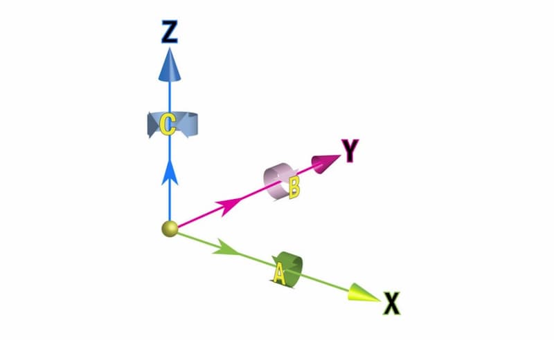
We have already mentioned the different axes in this article. But let’s make it fully clear what each means.
3-axis mill
A 3-axis vertical mill means that the table can move in 2 directions – X and Y. This enables to position the workpiece relative to the cutting tool while the distance remains the same. So the third, Z-axis, is added by allowing to lower the cutting tool.
CNC controllers enable simultaneous movement of the three, providing the necessary flexibility for most processing needs.
4-axis mill
A 4-axis mill has all the 3 axes as previously described. But another one comes in – the A-axis. Now the table can rotate around the X-axis, allowing face milling the sides without repositioning of the workpiece.
5-axis mill
As you can guess, all that was true for the 4-axis mill also applies to the 5-axis one. But now we add the B-axis which gives rotational movement around the Y-axis.
5-axis CNC machining centres cost a lot more than the other options but make it possible to produce very complex parts in one go. No extra setups are necessary while the tool life increases by making the suitable part positioning possible.
6-axis mill

ARVE error: url: https://www.googleapis.com/youtube/v3/videos?part=snippet%2Cstatistics&id=wOPt0dMP6ZA&key=AIzaSyAQ7WFzTAUrOX-FjsIrFS3JwZBFzgIvloc Status code 200 expected but was 403.
6-axis CNC milling centres are not too common because of the hefty price tag. They can be up to 75% quicker than 5-axis machines but the necessity of such capabilities is rare enough to justify the expenses. The video above also shows a comparison of a 5-axis and 6-axis mill.
The 6-axis mill has a stationary worktable and all the freedom of movement is allocated for the cutting head. It can move in 3 directions as well as rotate around all these axes.
CNC Milling Operations
Milling is suitable for many different features, including threading, chamfering, slotting, etc. This allows for producing complex designs on a single CNC milling centre with enviable accuracy. The tolerances for CNC machining are around +/- 0.1 mm.
The creation of these aforementioned features requires a variety of different milling operations:
- Surface milling
- Face milling
- Angular milling
- Form milling
- Profile milling
- Gear milling, etc.
Plain milling

ARVE error: url: https://www.googleapis.com/youtube/v3/videos?part=snippet%2Cstatistics&id=qZF3S-LfVks&key=AIzaSyAQ7WFzTAUrOX-FjsIrFS3JwZBFzgIvloc Status code 200 expected but was 403.
Plain milling is also commonly known as surface milling. It uses a horizontal mill, meaning the cutting tool’s rotational axis is parallel to the cutting surface.
Surface milling can use different cutters, wide or narrow, depending on the necessary outcome. Using a wide cutter can result in fast material removal when coupled with slow cutting speed, fast feed rate and coarse teeth of the cutter. Of course, the surface finish of such cutting may not meet the requirements.
Therefore, a second step can include a change of tools to use finer teeth. This also requires faster cutting speeds and slower feed rates, so the amount of material removal per time unit is slower. At the same time, the final finish is more accurate. Thus, the combination of the two makes for a good choice from an economic standpoint.
Face milling
ARVE error: url: https://www.googleapis.com/youtube/v3/videos?part=snippet%2Cstatistics&id=20PG1BG8YTY&key=AIzaSyAQ7WFzTAUrOX-FjsIrFS3JwZBFzgIvloc Status code 200 expected but was 403.
This operation uses a cutting tool that has teeth on the sides as well as on the end. The tool’s axis is perpendicular to the machined part.
Face milling often comes after surface milling, as it can produce more intricate contours and leaves a nice finish. The teeth on the sides do most of the cutting work while the teeth on the tip take care of the surface finish.
Angular milling

ARVE error: url: https://www.googleapis.com/youtube/v3/videos?part=snippet%2Cstatistics&id=A0H7SYv4oIE&key=AIzaSyAQ7WFzTAUrOX-FjsIrFS3JwZBFzgIvloc Status code 200 expected but was 403.
This milling operation lets us create chamfers, grooves, etc. There are several ways to accomplish these features.
In the case of a regular 3-axis mill, the use of different cutters makes the most sense. These can be dovetail cutters to produce angled grooves or just a mill with a conical cutting head for chamfering. Note that these two are basically the opposites of each other.
The axis of the cutter can be perpendicular or in line with the surface.
Form milling
ARVE error: url: https://www.googleapis.com/youtube/v3/videos?part=snippet%2Cstatistics&id=Ho1MjQHPbhM&key=AIzaSyAQ7WFzTAUrOX-FjsIrFS3JwZBFzgIvloc Status code 200 expected but was 403.
This type of milling requires special tooling to create more complex surface contours. Convex and concave cutters are both examples of tooling that find use here.
Form milling helps to create these surface contours in a single cut. The tools can help create round recesses, round edges, etc. The tools must have the right parameters to achieve the desired outcome.
Gang milling is a sub-category of form milling whereby utilising several cutters at once can create patterns.
Profile milling

ARVE error: url: https://www.googleapis.com/youtube/v3/videos?part=snippet%2Cstatistics&id=_jJrvmzQv-E&key=AIzaSyAQ7WFzTAUrOX-FjsIrFS3JwZBFzgIvloc Status code 200 expected but was 403.
A common milling operation to produce convex and concave parts. The process includes 3 steps – roughing, semi-finishing and finishing.
Roughing uses round inserts to do the initial work for removing most of the material. Ball-nose end mills are the perfect fit for semi-finishing and finishing.
Such work will largely benefit from CNC milling, as 4 and 5-axis technology can considerably quicken the operations as well as provide better quality.
Gear milling

ARVE error: url: https://www.googleapis.com/youtube/v3/videos?part=snippet%2Cstatistics&id=gfvTdZH23Fk&key=AIzaSyAQ7WFzTAUrOX-FjsIrFS3JwZBFzgIvloc Status code 200 expected but was 403.
Yes, milling also finds use for producing different types of gears. The whole process of producing gears comprises of two steps.
First comes gear milling. The material softness enables creating the part with more ease while achieving great tolerances. The gears then go through a heat treatment process to harden the surface. After that, CNC turning will be responsible for the final outcome.
Suitable Materials
CNC milling can be used on a variety of different materials. The choice, of course, comes down to the requirements. The selection process comprises of these steps:
- Creating the part geometry.
- Determining the forces acting upon the part. CAD software with FEA addons can be of much help here.
- Specifying the material properties based on the results.
- Creating a list of possible materials.
- Choosing one that fulfils the requirements with the best ratio for cost-efficiency.
- Making sure that the material is suitable for milling.
So, we can help you with the last step here.
Metals suitable for CNC milling:
- Mild steel
- Stainless steel
- Tool steel
- Aluminium
- Brass
Plastics suitable for milling:
- ABS
- Nylon
- Polycarbonate
- POM
- PTFE
- HDPE
- PEEK
After making your choice, it’s time to choose a reliable manufacturing contractor for the job. If you are looking for someone to help with milling metals, you can simply contact our sales engineers.
