

Finite Element Analysis software, also known as FEA software, is a common tool for every mechanical engineer today.
In the current market, there are many challenges to face in order to keep competitive. High profitability needs high quality products. Thus, product development engineers, QA engineers, reliability engineers, design engineers, etc. have to do their utmost to achieve that quality.
Some of the challenges include performing tests to make sure the parts and materials of their products behave as expected. That includes reactions to different situations including forces, vibrations and heat.
In the past, these tests were performed by creating a prototype of the product and performing the tests on it. However, creating prototypes and testing on them usually takes time and results in higher costs.
Using Finite Element Analysis, therefore, aligns very well with lean manufacturing methods in order to maximise productivity and minimise waste.
What is Finite Element Analysis?
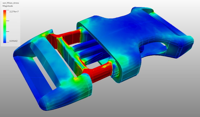
Finite Element Analysis (FEA) is a type of computerised analysis method. It is used to study simulated physical phenomena which is based on the Finite Element Method (FEM). FEM is a numerical method that uses mathematical models to solve complex structural engineering problems represented by differential equations.
Engineers use Finite Element Analysis in the design process. Instead of making prototypes for real-life experiments, they turn to Finite Element Analysis software.
Applying it during the design phase helps to optimise machinery parts to make better products and deliver them faster.
How to Use FEA in the Design Process?
There are different stages in the design process. One of them is testing out solutions to see if they meet the requirements and expected working behaviour.
First, the problem is defined. Market research is conducted in order to identify and specify the requirements. Then brainstorming and evaluation of different possibilities takes place. This includes modelling different parts and even whole assemblies by means of CAD software for better visualisation.
Fortunately, current CAD software usually comes in the form of a package that includes other modules beyond modelling. Many of them already include FEA capabilities. Of those, many even work with fluids which is known as Computational Fluid Dynamics or CFD.
Therefore, the models made in the previous stages of the design process can be used to test the possible solution. If necessary, redesigning the parts based on data and test results takes place.
Of course, it is also possible to export the models to another simulation software if necessary. Specialised software gives more accurate results and has more functions. For example, such optimisation is necessary for large-batch production. Over-dimensioning results in unnecessary costs that accumulate with series production.
Aspects to Consider in Applying FEA
Now, there are some aspects to consider when applying FEA in the design process:
- The type of analysis required must be clearly defined, which can be static or dynamic.
- The model must be FEA optimised. This is why CAD packages can be very powerful, as all the data of the CAD model is always available.
- Some hand-calculations must be performed. This is the only way to validate the FEA results. Check out our list of websites for mechanical engineers for great sources to perform these checks using online calculators.
Types of Analysis
You have to be sure to select the right analysis type to get the correct results.
Static Analysis

ARVE error: url: https://www.googleapis.com/youtube/v3/videos?part=snippet%2Cstatistics&id=Ds39pzecIHo&key=AIzaSyAQ7WFzTAUrOX-FjsIrFS3JwZBFzgIvloc Status code 200 expected but was 403.
It includes linear static and non-linear quasi-static situations. Some of the most common scenarios covered by static analysis include linear stress analysis, deformation analysis and thermal analysis.
Simple and complex structural analysis under specific loads are commonplace for static analysis.
Dynamic Analysis

ARVE error: url: https://www.googleapis.com/youtube/v3/videos?part=snippet%2Cstatistics&id=IjIJt7_P5UM&key=AIzaSyAQ7WFzTAUrOX-FjsIrFS3JwZBFzgIvloc Status code 200 expected but was 403.
It studies dynamic behaviours under dynamic loads, such as vibrational excitation. It includes modal analysis, harmonic response analysis, transient dynamic analysis and rotodynamic analysis.
Examples of dynamic analysis applications include the behaviour of engine components in different stages, such as the startup. It is also applicable for studying impacts outside the engineering realm. For example, you can create a simulation of a human skull’s reaction to impact.
- Personal account manager
- Quality assurance
- Payment terms for companies
- On-time delivery by Fractory
CAD Software with FEA Capabilities
Nowadays, there is a large variety of CAD and FEA software solutions being offered. With constant technological advances, it is easier to create more specific solutions with distinct features. The remaining question is – which of them suits you?
Incorporating FEA possibilities into the list of features is one of the big advantages of CAD software. Here we give you an overview of the most powerful CADs with integrated Finite Element Analysis tools. Highlighting the benefits and possible limitations of each makes it easier for you to choose the best option.
Autodesk Inventor

ARVE error: url: https://www.googleapis.com/youtube/v3/videos?part=snippet%2Cstatistics&id=teyRroZcX7E&key=AIzaSyAQ7WFzTAUrOX-FjsIrFS3JwZBFzgIvloc Status code 200 expected but was 403.
Autodesk first gained world-wide traction with the AutoCAD 2D drafting series. Now, Autodesk has grown into one of the top CAD and Finite Element Analysis software suppliers.
Inventor is Autodesk’s mechanical design and 3D CAD software. It includes classic CAD features such as parametric modelling, assembly modelling and drawing creation. But it also has more powerful new tools like design automation and automated frame design.
This software also allows you to work with sheet metal designs in a separate environment. It also provides great flexibility for visualisation such as exploded views and video animations.
Regarding Finite Element Analysis capabilities, you can easily run static or modal stress analysis and dynamic analysis on your models. The software provides a settings dialog box, a parametric table and a simulation guide to assist you with the simulation process.
In addition, Autodesk also offers Inventor Nastran, which they define as a CAD-embedded finite element analysis software. It is only available when subscribing to their Product Design and Manufacturing Collection.
This software should work as an extension to the FEA capabilities provided by Inventor. It includes a wider variety of studies and materials for your analysis. For example, the possibility of running linear and nonlinear stress, dynamics, and heat transfer studies.
Pros
- Powerful software from a prominent company.
- CAD embedded, thus file exports and imports are not necessary to run the studies.
- Customer support available in multiple languages.
- Great knowledge base in and out of the company’s website, including video tutorials, articles and forums.
- Assemblies and weldments can also be tested without the need for complex settings.
Cons
- Limited to linear stress and linear dynamic analysis. Other types require using Inventor Nastran.
- Inventor Nastran cannot be acquired as a stand-alone complement but only with a collection. The collection may include software you do not really need, and it can be pricey.
- Native only for Windows.
Dassault Systèmes SolidWorks
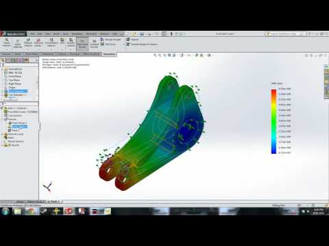
ARVE error: url: https://www.googleapis.com/youtube/v3/videos?part=snippet%2Cstatistics&id=lG_oSSo9vak&key=AIzaSyAQ7WFzTAUrOX-FjsIrFS3JwZBFzgIvloc Status code 200 expected but was 403.
One of the main competitors of Autodesk Invetor, SolidWorks is a 3D CAD software created in France. It prides itself on its design-to-manufacturing capabilities.
Among the main features found within SolidWorks, the possibility to work with large and complex assemblies stands out. It is possible to work on a simple model and scale into a full facility complex.
SolidWorks is a full CAD package with different modules including one of the best CAD-CAM softwares. These modules include:
- 3D CAD
- SolidWorks CAM
- Composer
- Electrical 3D
- Electrical Schematics
- Inspection
- Simulation, etc.
FEA is applied through the SolidWorks Simulation module. The module comes in three levels: Standard, Professional and Premium. Obviously the latter is the most powerful version and includes:
- Static studies
- Fatigue studies
- Motion analysis
- Thermal analysis
- Frequency studies
- Buckling studies
- Pressure vessel studies
- Topology optimisation
- Linear dynamic studies
- Non-linear analysis
In addition, the creator offers complements to SolidWorks Simulation. They range from flow simulation and plastic packages to more specific solutions. For example, the Electronics Cooling and Sustainability modules provide you with options to validate your design. All of these packages and modules are embedded in the 3D CAD software.
Moreover, to offer higher FEA capabilities to their users, Dassault Systèmes SolidWorks offers ABAQUS through their Simulia Structural Simulation Designer. It is a specialised FEA software that has great compatibility with the CAD interface.
Pros
- Powerful software from a prominent and validated company.
- CAD embedded, files exports and imports are not needed to run the studies.
- Wide range of tests within the same package.
- CFD tests can also be performed.
- Complements are offered as stand-alone solutions, giving you the possibility to only pay for what you really need.
- Customer support available in multiple languages.
- Great knowledge base in and out of the company’s website, including video tutorials, articles and forums.
Cons
- Depending on the version and number of modules you use, system requirements can be very high.
- Native only for Windows.
Siemens Solid Edge
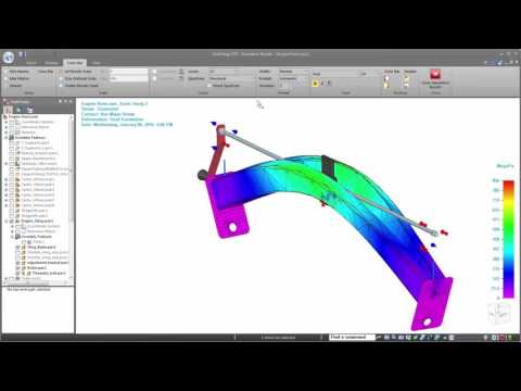
ARVE error: url: https://www.googleapis.com/youtube/v3/videos?part=snippet%2Cstatistics&id=515un5vL-2Y&key=AIzaSyAQ7WFzTAUrOX-FjsIrFS3JwZBFzgIvloc Status code 200 expected but was 403.
Solid Edge is a complete portfolio of product development tools offered by Siemens. The prominent German company offers tools for mechanical and electrical design, simulation, manufacturing, technical publications, data management and much more.
In the latest release of Solid Edge, we can find many new features. These include advanced technologies such as augmented reality and the ability to completely digitalise the design-to-manufacturing process.
Another outstanding feature included in Solid Edge is the optimisation for both additive and subtractive manufacturing. A range of manufacturing processes can be defined and executed, including:
- CNC machining
- Nesting
- Cutting
- Bending
- Moulding
- Welding
- Assembling
- Additive manufacturing
The latter is a nice addition due to the advancements in 3D printing technologies.
Solid Edge offers simulation tools in 3 different levels: Solid Edge Premium, Solid Edge Simulation and Solid Edge Simulation Advanced. Solid Edge’s scalable simulation lets the user digitally validate and optimise parts, assemblies and complete systems. You can do it early in the design process to reduce the need for rapid prototyping and save time and costs.
FEA capabilities in Solid Edge include simulation of individual parts, assembly analysis and computational fluid dynamics (CFD). With this CAD and Finite Element Analysis software it is possible to perform:
- Stress analysis and simulations
- Vibration simulations
- Full motion simulations
- Buckling simulations
- Thermal simulations
All options are based on proven Femap finite element modelling and NX Nastran solver technology.
Pros
- Powerful software from a prominent and validated company.
- CAD embedded, files exports and imports are not needed to run the studies.
- Wide range of capabilities within the same package.
- CFD tests can also be performed.
- Capabilities are scalable in a 3-level system for you to decide when higher costs are really justified.
- Customer support available in multiple languages.
- Great knowledge base in and out of the company’s website, including video tutorials, webinars, articles, forums and more.
- License can be acquired on an annual or a monthly subscription. It gives flexibility for the user to decide how to pay.
Cons
- Depending on the version you use, system requirements can be very high compared to other CAD and FEA software.
- The latest versions are limited to Windows 10 Enterprise or Professional.
PTC Creo
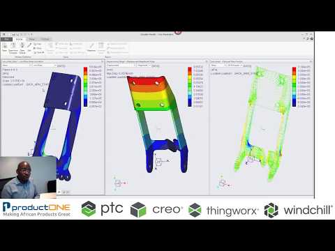
ARVE error: url: https://www.googleapis.com/youtube/v3/videos?part=snippet%2Cstatistics&id=P-YIh8xjjuw&key=AIzaSyAQ7WFzTAUrOX-FjsIrFS3JwZBFzgIvloc Status code 200 expected but was 403.
Creo is another well-known company in the design and engineering community. Their 3D CAD and Finite Element Analysis software is a tough competitor for the big names.
Creo offers scalable 3D CAD product development packages and tools. Those tools feature modelling and design, simulation and analysis, augmented reality and additive manufacturing.
In addition to the 3D design capabilities that you may find in any software, Creo offers possibilities for knowledge-based design. You can utilise real-world product usage data through their Smart Connected Design feature.
FEA capabilities in Creo have been scaling over the years. In the latest version, they have added CFD with the Creo Flow Analysis Extension. Another component is the Creo Simulation Live tool which provides instant feedback in the modelling environment.
Creo Simulation Live is the most remarkable feature, as it puts structural, thermal, and modal analyses into the hands of designers instantly. It is possible to perform simulations without the need to mesh or simplify models.
This technology was created in partnership with one of the most respected names in the engineering software industry, ANSYS. Therefore, Creo has definitely boosted their credibility and reliability in the market.
With Creo 6.0 it is possible to run:
- Structural analysis
- Thermal tests
- Motion analysis
- Fatigue simulation
- Mould fill analysis
All these possibilities make it a good option as a complete 3D CAD and Finite Element Analysis software.
Pros
- Powerful software from a prominent and validated company.
- CAD embedded, files exports and imports are not needed to run the studies.
- Wide range of capabilities within the same package.
- CFD and mould filling tests can also be performed.
- Capabilities are scalable in a 5-level subscription system for you to decide when higher costs are really justified.
- Customer support available in multiple languages.
- Great knowledge base in and out of the company’s website, including video tutorials, webinars, articles, forums and more.
- License can be acquired on pay-as-you-go model, which gives flexibility for the user to decide how to pay.
Cons
- Simulation limited to the Design Premium and Design Premium Plus tiers.
- Native for Windows only.
Final Thoughts
It is important to mention that we can find very powerful and specific Finite Element Analysis softwares such as ANSYS. These offer the possibility to run studies on more complex and specific engineering situations and fields. However, this type of software has no use as a separate CAD program. So they need to be used parallel to some of the programs we mentioned before.
If you are a student, a teacher, or a small business owner, you can often benefit from special offers. Some programs even make themselves free for learning purposes, so use this opportunity to choose the suitable one for yourself.
If you have your CAD models ready, you can submit them for an instant manufacturing quote on our online platform!
