

Engineers use CAD software to design all the necessary parts and components for the project. In the digital realm, it is easy to attain perfection. In real life, manufacturing is never 100% accurate.
Sometimes, deviations of a few millimetres from the basic dimensions can be absolutely fine. At the same time, two mating components could require extremely high accuracy.
To keep the expected deviation in a predefined range, it is possible to use engineering tolerances. Dimensional tolerances are very common but lack ways to communicate some very important aspects of manufacturing. This is where GD&T, or geometric dimensioning & tolerancing, steps in.
It is a form of describing dimensions and tolerances in a wholly new way. Using a common language of engineering symbols, it helps to pinpoint all the necessary information easily.
What Is GD&T?
It is a system of symbols and standards used by engineers to provide manufacturing information to the production team.
The reasons for using Geometric Dimensioning and Tolerancing (GD&T) are:
- It ensures that mating parts fit together well
- The universal language works regardless of who you are working with
- Tolerances give a limit to the worst-case conditions
- Defines production and inspection processes
Stanley Parker is credited with being the engineer behind the development of the GD&T system in 1938.
Before that, all features used only X-Y axes to determine the position of a hole, for example. Giving a positional tolerance on that scale means that the circular hole’s position can deviate in a rectangular pattern from the intended spot.
However, we would actually want the tolerance zone to be a circle, as this allows for a uniform measurement in all angles, whereas a rectangle is longer towards the corners and shorter towards the sides.
So, as Parker realised that, he started working on the new concept, which was adopted as a military engineering standard in the 50s.
Today, GD&T is an important part of engineering, especially when creating parts that require CNC machining services. The American standard describing the features is ASME Y14.5-2018, and the European equivalent is ISO 1101-2017.
GD&T focuses solely on the geometry of the product. Linear dimensions, surface roughness, threads, etc, are not part of this standard.
Why Implement GD&T?
We do have traditional methods of denoting dimensions and tolerances. So what is the need for geometric dimensioning and tolerancing?
Geometric dimensioning and tolerancing (GD&T) offers some unique advantages over regular methods. Let’s see what these are.
Perfect assembly
The most important drawback of using traditional dimensioning and tolerancing is that they denote individual part and part feature information. It does not guarantee how well our parts will fit and function at the assembly level.
This is important because most parts are not useful by themselves. Consider the example of a connecting rod. By itself, it doesn’t provide us with any benefit. But when we connect it to the crankshaft and the piston, it becomes a bit more useful, as it converts the linear motion of the piston into rotational motion of the crankshaft.
When this assembly becomes a part of a larger assembly such as a diesel engine, it can end up as a part of a generator that provides us with many uses.
Thus, it is crucial that our parts mate well with each other. This is why we need GD&T. Using it, we can be 100 per cent certain that our parts will fit together and function exactly as needed.
A common system to explain the design intent
GD&T also provides the designer with a platform to convey their design intent to all the relevant departments. These include:
- Manufacturing
- Inspection
- Future designers in the design department who will pick up work if the initial design team is not available
The definitions, vocabulary and rules are straightforward and universally understandable. This makes the symbols easy to translate for every engineer and a great way of conveying the designer’s intention.
Saves time and money
This is the most important benefit of using GD&T. Using this system reduces wastage as it cuts down the number of design-manufacturing-test fit cycles.
This is because manufactured parts fit well at the first attempt and consequently, the number of rejects will be low. Using a common language also reduces the effort necessary for inspection.
- Personal account manager
- Quality assurance
- Payment terms for companies
- On-time delivery by Fractory
What to Consider?
Geometric dimensioning and tolerancing is a more powerful system compared to traditional tolerances. However, it only works if all departments (design, engineering, and manufacturing) are well-versed in reading and interpreting the information.
Therefore, while creating engineering drawings and tolerancing various part features, it is important to follow the recommended guidelines/conventions for the benefit of everyone who will interact with the drawing at any stage of product development.
Observing them ensures that the drawing is standardised and everyone is on the same page when it comes to drawing specifics. Some of these good practices are as follows.
Intelligibility of the drawing
This is arguably the most important quality of a drawing. The intelligibility refers to the clarity with which part features are drawn and tolerances are shown in the drawing. Some ways to improve the intelligibility of a drawing are:
- Draw true profiles for all part features.
- Label dimensions and tolerances outside the drawing (not on top). Use white space effectively.
- Reading direction must be constant. A reader should be able to read all dimensions while holding the drawing upright.
- Space out dimensions of parallel part features.
- Explain the part and its function briefly.
- Specify angles only when they are not right angles (90°).
Tight tolerances only when necessary
Unless a part fit/function demands it, tolerances must be kept as loose as possible. This reduces the manufacturing cost and turnaround time. We recommend leaving the choice of manufacturing method to the machinists.
The designer must also mention the general tolerance for a drawing. This acts as the standard tolerance for all part features. For parts with features with a different tolerance limit, the designer must mention them at appropriate positions.
These specific tolerance limits will override the general tolerances. When specifying special tolerance limits, prefer functional features over other features.
GD&T Features & Symbols
The GD&T language is able to define pretty much any qualities that are necessary for ensuring a perfect assembly.
The system uses a number of symbols for this purpose. To use these engineering symbols on drawings correctly, we must first be familiar with some basic building blocks of this system.
We can start with the various definitions, terminologies, and rules before we get to GD&T symbols.
Nominal dimensions
A nominal dimension is the feature size of the true profile. It is the exact dimension that we would like to achieve ideally. Feature specifics such as size, orientation, and the location from a reference point have a nominal size that machinists target.
On a drawing, they are shown within a box. It may be shown as a number or from a popular standard such as ASME.
Feature control frame
This frame contains information about part specifics. It contains various compartments where each compartment defines a specific attribute of the part feature. At a glance, the feature control frame conveys the information required for machining and inspection.
The feature control frame can be divided into 4 main parts as follows.
Leader arrow
This arrow marks the part feature under control. If it leads to a surface, the surface is under geometric control. If it marks a diametric dimension, then GD&T controls the axis. This arrow may not be present in some cases.
Geometric characteristic symbol
The first compartment (starting from the left) contains the geometric characteristic symbol. This is where we specify the geometric characteristic. In total, there are 14 types of geometric tolerances based on the number of symbols, and 15 when classified.
The different types of geometric characteristics are form control, profile control, location control, orientation control, etc. We will dive deeper into each category later on.
Feature tolerance compartment
The 2nd block contains a maximum of 3 (sometimes 2 or 1) different symbols.
The first symbol shows the type of tolerance zone. A diameter symbol (⌀) signifies a diametric zone (cylindrical tolerance zone). To specify a spherical zone, the symbol is the letter ‘S’ followed by the diameter symbol (⌀). In the absence of a symbol, we assume a total wide zone.
The second symbol in the 2nd block gives the value of the tolerance zone in mm. This value must always be present in the 2nd block.
The third symbol in this block is the modifier for tolerance. This material modifier is only present when the feature has a size, for instance, a hole. Examples of material modifiers are MMC (Maximum material condition) and LMC (Least material condition). More information on the various modifiers available will be discussed further in the article.
Datums
The third block gives information about the datum(s) with a minimum of 1 and a maximum of 3 datums. In the case of 3 datums, they are referred to as primary, secondary, and tertiary datums with each being shown enclosed in a different box (the image above has 2, for example). This block may also contain a material modifier.
All the information above helps us to understand how to read a feature control frame. In order to better understand how tolerance can be adjusted using material condition modifiers, we need to be familiar with the different options.
Material Condition Modifiers
Material condition modifiers convey the intent when tolerance applies to a feature at a specific feature size. Whenever we give tolerances to any feature, it establishes two material conditions
- Maximum material condition
- Least material condition
Consider a shaft of diameter 100 mm. When manufacturing, if we give it a tolerance of ±0.2 mm, then at 100.2 mm, the shaft will contain the maximum amount of material. This is what we mean by the maximum material condition.
On the other hand, the same shaft, when manufactured with a diameter of 99.8 mm, will contain the least amount of material. These limits are called material conditions.
The geometric tolerances can be applied to a feature in 3 different ways. These are as follows:
- Maximum material condition
- Least material condition
- Regardless of feature size
Maximum material condition modifier

We represent this condition by a circled “M” after the tolerance value in the feature control compartment. The feature contains the maximum material at this feature size.
For external FOS (Feature Of Size), such as the diameter of a shaft, MMC represents the largest size. For internal FOS, such as the diameter of a hole, MMC represents the smallest possible size within stated tolerance limits because a smaller hole means that more material will be left.
When we need to apply geometric tolerance at the maximum material condition, we mention this condition in the feature control frame.
Least material condition modifier
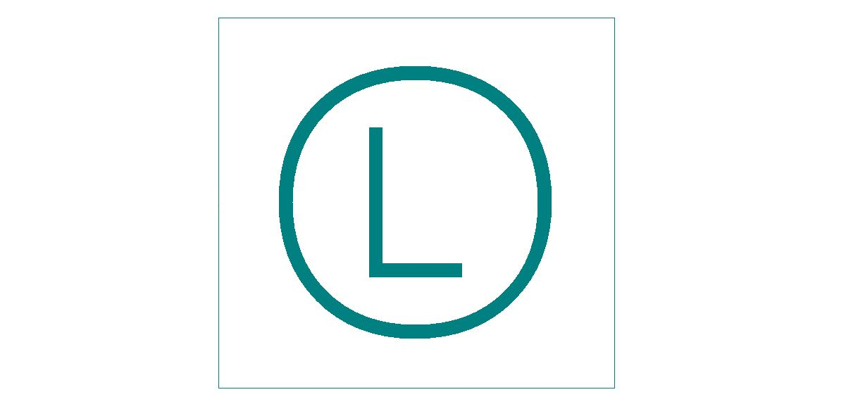
LMC is the condition where the material contains the least amount of material.
For external FOS, it will be the smallest possible size within stated limits. And for internal FOS, it will be the largest possible size.
We represent this modifier with the letter “L” in a circle. This feature removes excessive material and thus weight. To apply geometric tolerances at this condition, we use its symbol in the feature control frame.
Regardless of Feature Size (RFS)
When the given geometric tolerances are applied at any increment of size of FOS, we indicate this by RFS. The symbol for RFS was the letter “S” enclosed in a circle but it is no longer needed as RFS is considered the default condition now, and does not need a symbol.
Datums and Feature Callouts
Datums are reference points for measuring dimensional tolerances. It could be a point, a line, or a plane. With the help of a datum, we establish Datum Reference Frames (DRF). The DRF is basically a 3D coordinate system that helps us define the positions of all other features with respect to the DRF.
There are 6 degrees of freedom (3 translational and 3 rotational) that we need to control to manufacture and inspect parts effectively. We use DRF to establish these degrees of freedom.
Datum features are the actual part features, such as holes and slots. They can show variation from desired positions.
Among all the datum features, we give the highest preference to those that mate with other parts in the assembly. We can mention more than one datum in our feature control frame. As per the sequence of the DRFs in the feature control frame, the parts are mated to the DRFs in decreasing order of importance.
GD&T Symbols
Up to 14 GD and T symbols are available to represent different geometric characteristics of features. These symbols help us to specify these characteristics as requirements for the final product.
We place these symbols in the first compartment of the feature control frame. We shall look at these types of tolerance control.
Form control
As the name suggests, form control relates to the final form or shape of the feature. We define form controls to limit the deviation of the geometric tolerance from its ideal form. Some popular form control characteristics are as follows.
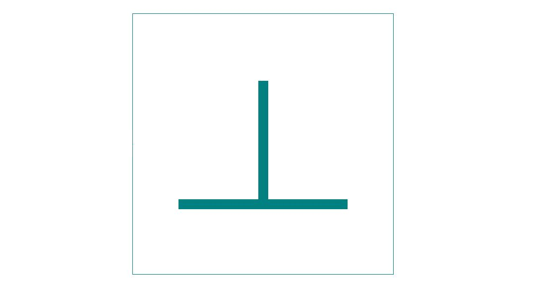
Straightness
To indicate the straightness characteristic of a feature (such as an axis or a surface), we use its symbol (a straight horizontal line) in the first compartment.
Surface straightness can apply to flat surfaces like a side of a block or curved surfaces like a side of a cylinder along the direction of the axis. It defines the allowable variation of a line (2 dimensions) on the surface within a specified tolerance.
Axial straightness usually applies to the axis of a shaft or a hole, for example. Go/no go gauge is the inspection tool used in the process of making sure the part conforms to the demands.
Flatness
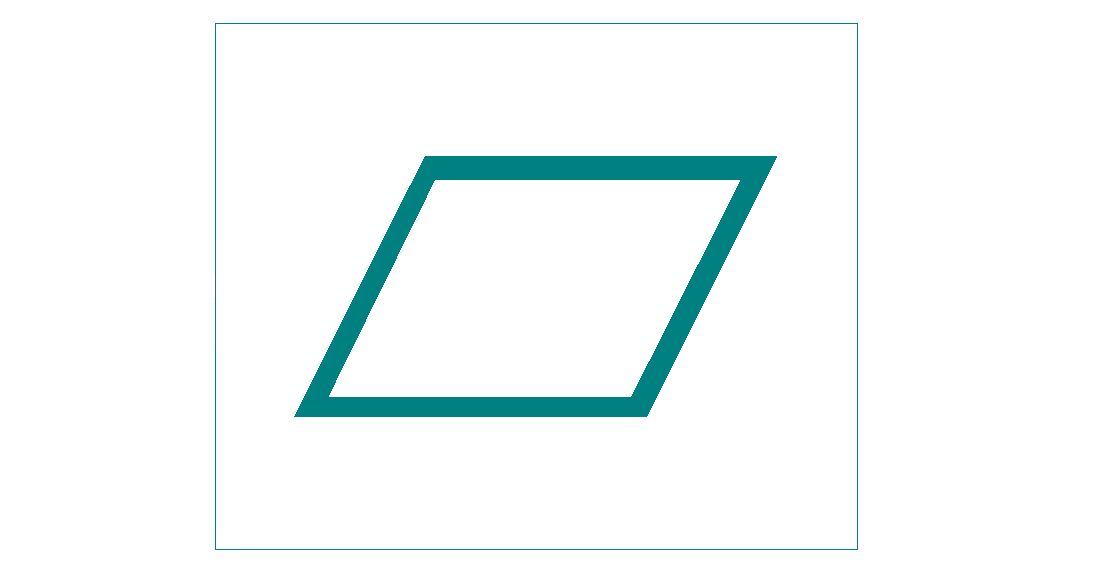
We use this characteristic for features such as the face of a part. The symbol for flatness is a parallelogram tilted to the right. The difference between the highest and lowest point of a flat surface is its flatness.
The flatness symbol does not require any datums, as it only shows a tolerance range within which the whole surface of a part must conform to in 3 dimensions.
A height gauge is used for checking the results. It touches upon different areas of the surface to determine that all the points are inside the tolerance zone.
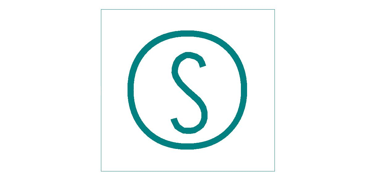
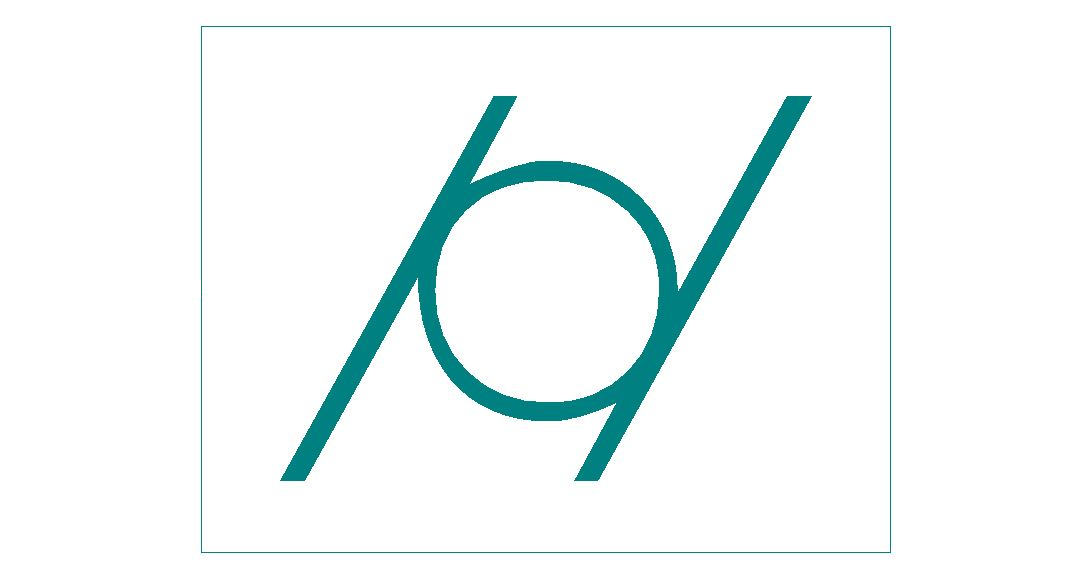
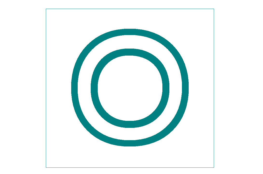
Circularity
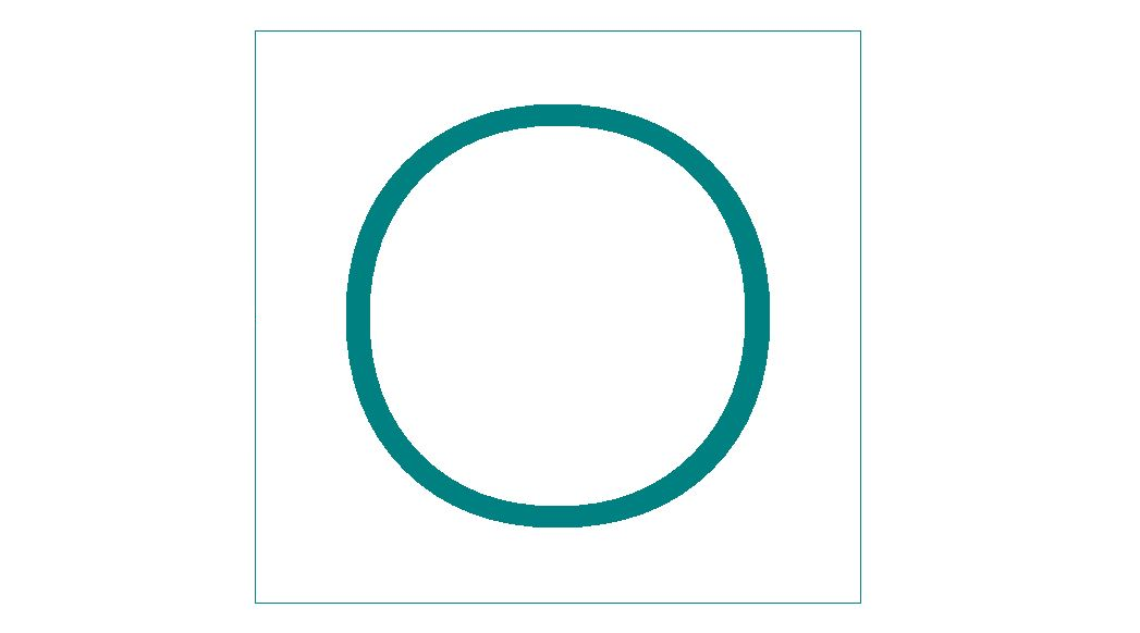
The circularity (GD&T) of a feature shows how close the circumference of the part should be to a perfect circle. It uses 2 concentric circles on a plane perpendicular to the part axis to define the suitable tolerance range in 2D. Each point of the final measurements has to fall between the circles.
This characteristic is shown as a circle in the first compartment of the feature control frame.
Cylindricity
Cylindricity is basically circularity in 3D, meaning that it runs along the whole length of the part.
This feature also describes other cylindrical characteristics such as its taper, straightness, and roundness. This is why this feature is also expensive to inspect.
Profile Controls
We use profile controls to control the 3D tolerance zone around the feature. This feature helps us to give tolerance limits to advanced curves and shapes.
A feature that is good for advanced curves must naturally work well with simpler curves as well. This makes profile controls extremely versatile. This is why some designers recommend abandoning all other controls and working only with profile controls.
These controls form a tolerance limit around the advanced curve by mimicking it on both sides. It then prevents any point on the feature curve from going outside the tolerance limit. Profile controls are of two types.
Line profile
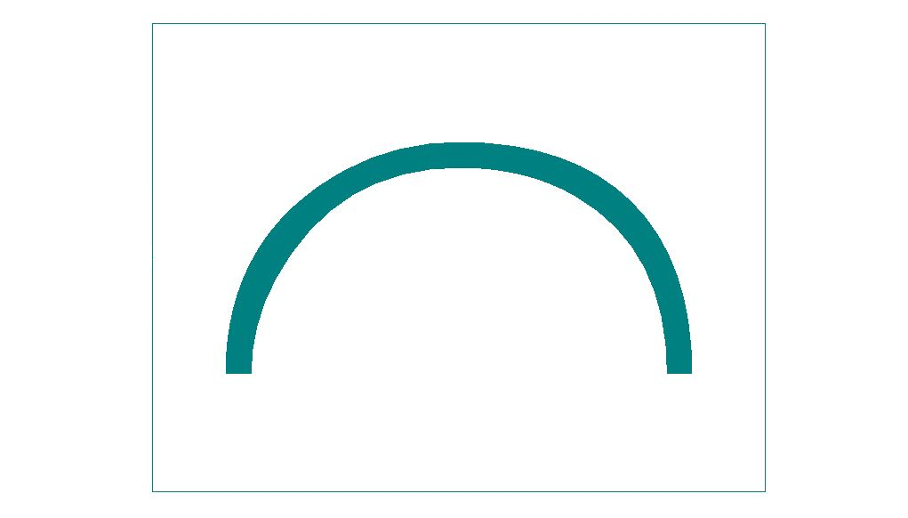
Line profile (profile of a line) establishes a tolerance zone around varying 2D cross-sections of the part. It controls individual line elements of a part feature.
The line profile control traces the ideal curve at the tolerance limits on both sides. All points on the part’s curve must lie within these limits.
Surface profile
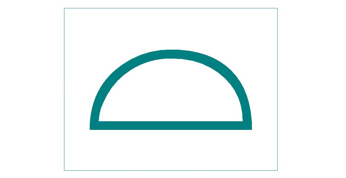
Surface profile control is more popular compared to line control. Instead of a two-dimensional tolerance zone, the surface profile control creates a 3D zone around a surface.
All points on the table’s surface must lie within the two virtual planes.
Orientation Controls
Orientation tolerance controls the orientation of a feature with respect to a defined datum. There are three types of orientation controls in GD&T.
Angularity
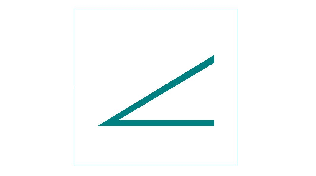
The angularity control keeps the angle of a feature with respect to the datum in check. We can use it to control a 2D line, but it is more popular with keeping surfaces (3D) under control.
This kind of tight control keeps the angle and the surface flatness in check and is recommended for part features that mate with other parts through the angled surface.
It is important to note that the angularity feature controls the angle indirectly, not being essentially the same as an angular tolerance (e.g. +/- 2°). Rather, the necessary angle is a result of keeping to the dimensional requirements laid out by this control.
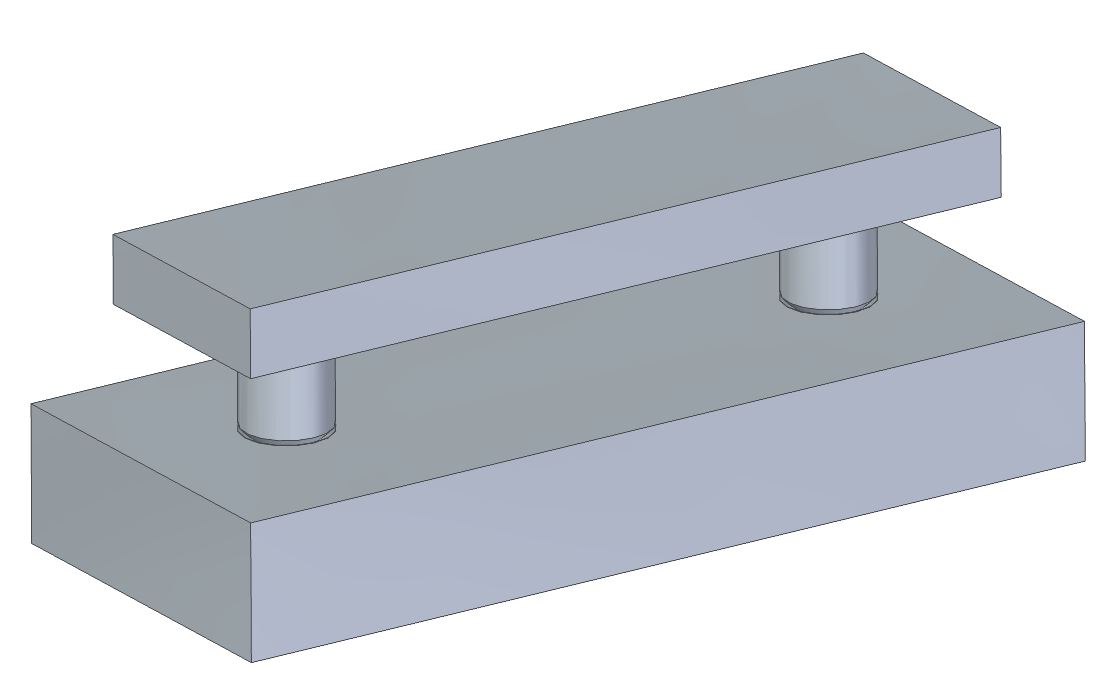
Parallelism
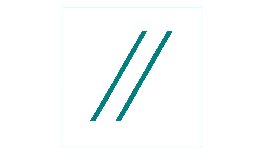
Parallelism is a refined form of angularity. Here, the datum is the surface we need to imitate and the angle is set to 0°. There are 2 types of parallelism: surface parallelism and axis parallelism.
We can choose an axis or a surface as a reference. This becomes our datum and we reference it in the 3rd block of the feature control frame as the datum for the feature.
Similarly to angularity, it does not control the actual angle but rather secures it by laying out the requirements in the form of a tolerance zone.
Perpendicularity
Perpendicularity is also a specific form of angularity where the angle is set to 90°. It is a tricky control since it can mean two very different types of requirements.
There’s surface perpendicularity ( Symbol:⟂), and then there’s axis perpendicularity (Symbols: ⟂+⌀).
Surface perpendicularity specifies that a surface or line needs to be perpendicular to a datum surface or line much like angularity. Two virtual planes/lines are assumed around the target surface for control.
Axis perpendicularity specifies how perpendicular an axis needs to be to the mentioned datum. This is done by erecting a virtual cylinder around the target axis on a surface exactly parallel to the datum surface.
Location Controls
The Location tolerance control is used for tight control on a feature’s position with respect to a datum. There are three main types of location controls.
Concentricity
Concentricity, also known as coaxiality (even though not exactly the same thing), control maintains the concentricity of circular as well as cylindrical features.
It fixes the axis of a part to the axis of a referenced feature (datum axis). The axes of both parts are determined to be at the median points of the parts.
This control can lead to some confusion because the axes derive from outside measurements, rather than their actual placement.
Coaxiality creates a 3D tolerance zone based on surface measurements that the part must lie in.
Symmetry
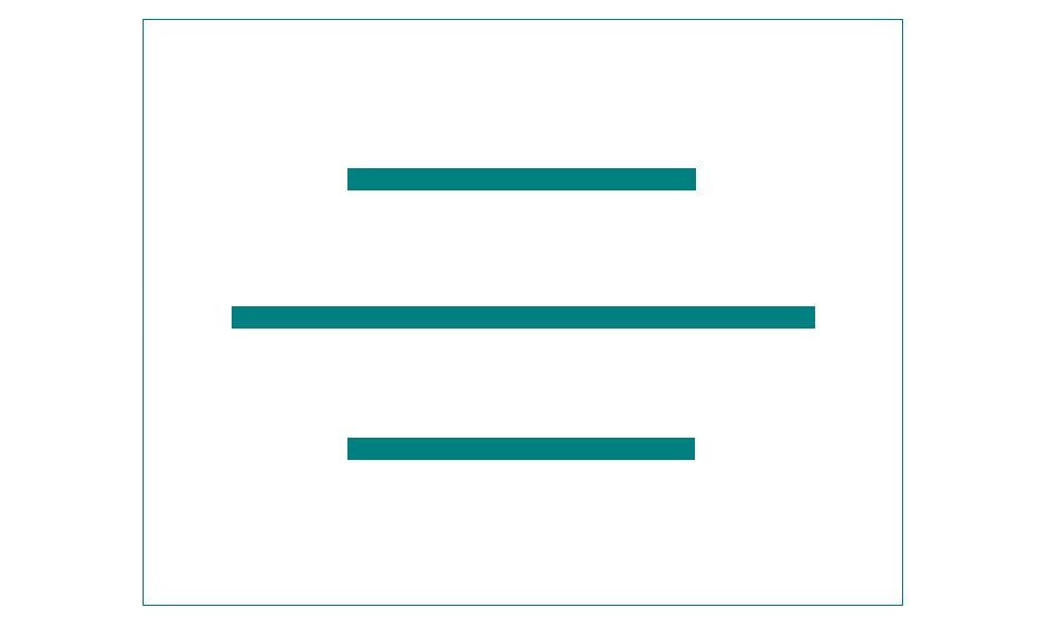
The symmetry callout establishes a central plane around which the two parts of the feature are placed at equal distances. The midpoint of the two points on either side must lie within the tolerance zone set around the central plane.
The symmetry callout is not very common. It has very limited uses and is also difficult to inspect. We need a CMM to inspect the final symmetry.
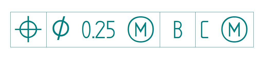
True position
True position (popularly known as position) is a very useful callout and finds extensive use in GD&T.
Position defines how much the actual position of a feature can vary from its intended position. The definition includes the datum plane which the measurement relates to.
It often includes a diametrical sign (⌀) to highlight that the tolerance zone is a circle, rather than just X and Y axis (which we talked about at the start of the article as being the reason for creating GD&T in the first place).
Here is a great video showing how to use the tolerances on a drawing, using true position:

Runout Controls
We use the runout controls to measure the deviation of a part feature from its assigned position with respect to an established datum. This control is used for circular features. It essentially measures its wobble by rotating the feature about the fixed datum.
There are two types of runout control.
Circular runout
Circular runout works in two dimensions to control the form, location, and orientation of various part features. This 2D callout needs us to assign it a datum axis to check these features.
In GD&T jargon, circular runout is commonly known as runout. Runout measures the deviation in the surface elements by rotation.
Meaning that the shaft, for example, is rotated by its datum axis and the featured element is measured for tolerance. In essence, it limits the vibration of a working shaft to ensure a longer lifetime for connected parts like bearings.
Total runout
Total runout is the 3D counterpart of circular runout. It controls form, location, and orientation as well. But instead of checking individual cross-sections (as in circular runout), it checks the entire surface. Thus, using total runout gives us stricter control on the feature’s characteristics.
Inspection
In all industries, the failure of the manufacturing process to meet design specifications can be problematic. While in some cases, customers’ lives may be at risk, in other cases, a product recall could lead to huge monetary losses.
Even if the results are not that bad, a company’s reputation relies heavily on the quality of its products and services.
GD&T standardises the inspection process by bringing inspectors in on the same platform as the designer. This eliminates a lot of obstacles. But GD&T is a vast subject.
As we have seen, there are a number of different geometric characteristics, each very different from another, that can be controlled with GD&T. Due to this disparity, the inspection of each characteristic requires a specific method, tool, and skill.
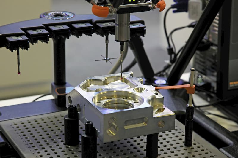
Some of these characteristics can be measured with the simplest of tools while others are impossible to measure without advanced equipment such as a coordinate-measuring machine (CMM).
Inspectors will need the knowledge and skill to use various measurement tools such as dial gauges, micrometres, vernier callipers, surface plates, and coordinate-measuring machines to inspect the accuracy of parts satisfactorily.
